A Split Drilling Milling Pipe Cutting Machine

A split-type, pipe cutting machine technology, applied in milling machine equipment, details of milling machine equipment, metal processing machinery parts, etc., can solve problems such as inapplicability to oil and gas pipeline maintenance and repair sites, achieve simple structure, easy implementation, and ensure stable work. Effect

Inactive Publication Date: 2016-06-08
SHENYANG LIAOHAI PETROLEUM & CHEM ENG
View PDF9 Cites 0 Cited by
  • Summary
  • Abstract
  • Description
  • Claims
  • Application Information

AI Technical Summary

Problems solved by technology

[0005] However, drilling machines and milling machines are large devices, which are only suitable for the interior of enterprise workshops, with fixed positions, and are not suitable for maintenance and repair sites of oil and gas pipelines.

Method used


Image

  • A Split Drilling Milling Pipe Cutting Machine
  • A Split Drilling Milling Pipe Cutting Machine
  • A Split Drilling Milling Pipe Cutting Machine

Examples


Embodiment Construction

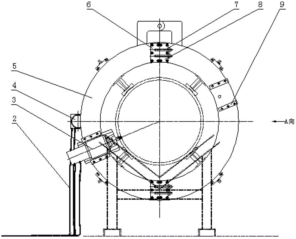
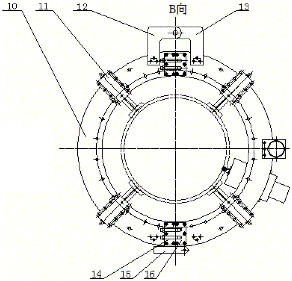
[0038] Such as figure 1 , 2 As shown, the present invention relates to a split drilling and milling pipe cutting machine, which has a fixed seat 10, an adjusting leg 11, a movable seat 5, a circular feed drive part 4, a drilling and milling head part 3 and a power source, wherein: The fixed seat 10 is a split structure, supports and connects the various parts of the pipe cutting machine, and positions the relative positions of each part; the adjusting leg 11 is installed on the rear end surface of the fixed seat 10, and the fixed seat 10 is fixed by the adjusting leg 11 to the outer wall of the pipe to be cut; the movable seat 5 is a split structure, and is connected to the front end of the fixed seat 10 through a rolling device; the circular feed drive part 4 is installed on the outer edge of the fixed seat 10, and the 5 transmission connection; the drilling and milling head part 3 is installed on the front end of the movable seat 5, the drilling and milling head part 3 is e...


PUM


Abstract

The invention relates to a split drilling and milling pipe cutting machine. The outriggers are fixed on the outer wall of the pipe to be cut; the movable seat is a split structure, and is rotationally connected with the front end of the fixed seat through a rolling device; the circular feed drive part is installed on the outer edge of the fixed seat, and is connected by transmission with the movable seat The drilling and milling head part is installed on the front end of the movable seat. The milling cutter is installed on the drilling and milling head part and drives the milling cutter to perform the main movement of rotating cutting and the radial feeding movement along the radial direction of the pipeline; the power source drives the circular feed Drilling and milling pipe operations are completed for the drive unit and the drilling and milling head unit. The present invention is simple in structure and easy to implement. The milling cutter only needs to cut once around the pipe circumference to complete the pipe cutting work. Cutting work for strength steel pipes.

Description

technical field [0001] The invention relates to a rapid maintenance and emergency repair equipment for fluid pipelines, in particular to a split-type drilling, milling and cutting machine. Background technique [0002] With the continuous development of my country's petroleum industry, petroleum and natural gas pipeline transportation occupies an extremely important strategic position in the national economy. The basic requirements for oil and gas pipeline transportation are safety and efficiency. Once a pipeline accident occurs, not only will it cause huge economic losses, but it will also have serious consequences for society and the environment. The direct or indirect economic losses are huge, and the repair costs are also very high. Therefore, it is extremely important to pay attention to the rapid maintenance and emergency repair of oil and gas pipelines, to carry out timely and effective maintenance and emergency repairs to the accident pipelines in the shortest time,...

Claims


Application Information

Patent Timeline
Patent Type & Authority Patents(China)
IPC IPC(8): B23C3/00B23Q1/01B23Q5/06B23Q5/40
Inventor 王平解发光张玖山罗瑞奇吴明
Owner SHENYANG LIAOHAI PETROLEUM & CHEM ENG
Why Eureka
Try Eureka