Multistage-protection hydraulic device

A technology of hydraulic devices and electromagnetic reversing valves, which is applied in the direction of fluid pressure actuation devices, fluid pressure actuation system safety, mechanical equipment, etc., and can solve the problems of frequent failures, unloading valves and solenoid valves, and no protection measures and other problems to achieve the effect of ensuring non-stop

Inactive Publication Date: 2014-02-12
SHANGHAI PUDONG HANWEI VALVE
View PDF7 Cites 3 Cited by
  • Summary
  • Abstract
  • Description
  • Claims
  • Application Information

AI Technical Summary

Problems solved by technology

[0003] In the prior art, two sets of piping systems generally share one unloading valve and one solenoid valve, and the unloading valve and solenoid valve work frequently and are most prone to failure. Once a failure occurs, there

Method used


Image

  • Multistage-protection hydraulic device

Examples


Embodiment Construction

[0031] The present invention will be further elaborated below by describing a preferred specific embodiment in detail in conjunction with the accompanying drawings.

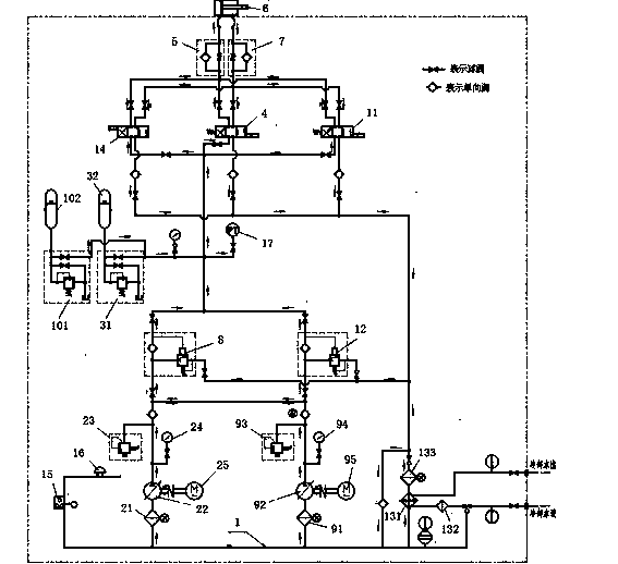
[0032] Such as figure 1 As shown, a hydraulic device with multi-stage protection includes an oil tank 1 connected through pipelines, a first oil pump assembly, a first unloading valve 8, a first energy storage control assembly, a first electromagnetic reversing valve 4, an inlet Oil throttle valve 5, oil cylinder 6 and oil return throttle valve 7; when oil is fed, hydraulic oil is sent to oil cylinder 6 through oil tank 1, first pump oil component, first energy storage control component, and oil inlet throttle valve 5 in sequence ; When returning oil, the hydraulic oil flows out from the oil cylinder 6 and returns to the oil tank 1 through the oil return throttle valve 7 and the first electromagnetic reversing valve 4 . The first unloading valve 8 is also provided with an oil discharge port, and the oil discharg...


PUM


Abstract

The invention discloses a multistage-protection hydraulic device which comprises an oil tank, a first oil pumping assembly, a first energy storage control assembly, a first electromagnetic reversing valve, an oil feeding throttling valve, an oil cylinder and an oil return throttling valve which are connected through a pipeline. The device further comprises a second oil pumping assembly, a second energy storage control assembly, a second electromagnetic reversing valve and a second unloading valve. An inlet of the second oil pumping assembly is connected with the oil tank, and an outlet of the second oil pumping assembly is connected with an outlet of the first oil pumping assembly. The second energy storage control assembly is connected onto an oil feeding pipeline between the second oil pumping assembly and the first electromagnetic reversing valve. The device adopts two hydraulic sources, one is operated, and the other is for hot spare onsite. Once one hydraulic source breaks down, the source is switched immediately onsite, greater damage to the device and caused by the fact that a worker needs to move from a control chamber to the site of the device is avoided, and the hydraulic device does not shut down. Further, energy storage devices, unloading valves, overflowing valves and electromagnetic valves are all arranged in two sets and can be optionally switched in use, and multistage protection can be achieved by means of combination use.

Description

technical field [0001] The invention relates to a hydraulic device, in particular to a hydraulic device with multi-stage protection. Background technique [0002] The 24-way rotary valve is the heart equipment of a petrochemical plant. If the 24-way rotary valve is shut down, all the equipment related to it will be stopped. If it is shut down for one day, the chemical plant will lose about 500,000 US dollars, and the hydraulic device is a 24-way rotary valve. The auxiliary equipment of the valve is also the core equipment. Its function is to provide hydraulic oil with sufficient flow and oil pressure to the hydraulic cylinder of the 24-way rotary valve to drive the action of the rotary valve. It is the power source of the 24-way rotary valve. It is required to ensure the flow and oil pressure. Long-term normal and trouble-free operation. [0003] In the prior art, two sets of piping systems generally share one unloading valve and one solenoid valve, and the unloading valve ...

Claims


Application Information

Patent Timeline
IPC IPC(8): F15B20/00F15B1/02
Inventor 吴志敏
Owner SHANGHAI PUDONG HANWEI VALVE
Why Eureka
Try Eureka