Phase shift mask and detection method for light transmission uniformity of slit of photoetching machine

A phase-shift mask and detection method technology are applied in the field of phase-shift mask and the detection of light transmission uniformity of lithography machine slits, which can solve the problem of measuring illumination uniformity and positioning that cannot be adapted to actual working conditions and cannot be accurately measured. Abnormal location, etc.

Pending Publication Date: 2022-07-01
SHANGHAI MICRO ELECTRONICS EQUIP (GRP) CO LTD
View PDF0 Cites 0 Cited by
  • Summary
  • Abstract
  • Description
  • Claims
  • Application Information

AI Technical Summary

Problems solved by technology

[0002] At present, the illumination uniformity test of the lithography machine mainly adopts the off-line measurement strategy, which is realized by the sensor inside the lithography machine. However, the sensor measurement adopts a fixed mode, which cannot adapt to complex and changeable actual working conditions. The final exposure result may be different from the sensor measurement. There is a difference in the results
The CDU that is often used in the process can also characterize the uniformity of illumination to a certain extent, but the CDU itself is the result of a combination of factors, and cannot accurately measure the uniformity of illumination and locate abnormal locations

Method used


Image

  • Phase shift mask and detection method for light transmission uniformity of slit of photoetching machine
  • Phase shift mask and detection method for light transmission uniformity of slit of photoetching machine
  • Phase shift mask and detection method for light transmission uniformity of slit of photoetching machine

Examples


Embodiment Construction

[0055] The present invention will be further described in detail below in conjunction with the accompanying drawings and embodiments. It should be understood that the specific embodiments described herein are only used to explain the present invention, but not to limit the present invention. In addition, it should be noted that, for the convenience of description, the drawings only show some but not all structures related to the present invention.

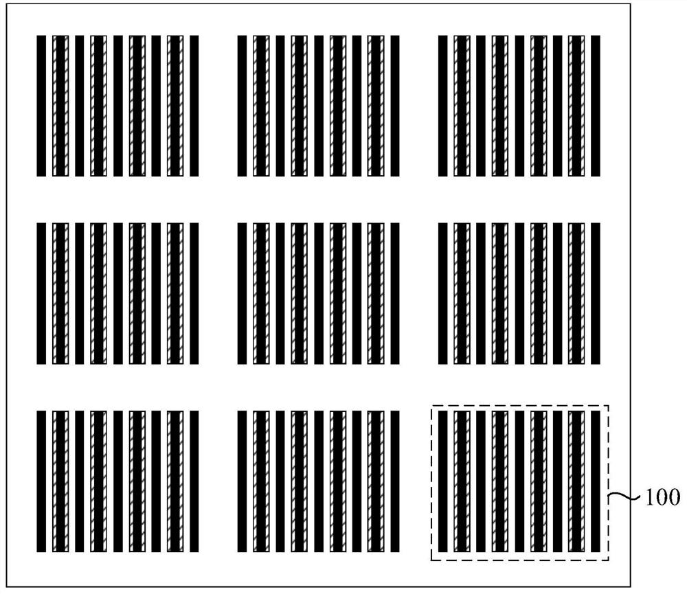
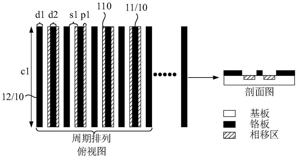
[0056] figure 1 is a schematic structural diagram of a phase shift mask provided by an embodiment of the present invention, figure 2 Yes figure 1 The structure diagram of the marked pattern in the phase shift mask shown, refer to figure 1 and figure 2 , First of all, the phase shift mask provided by the embodiment of the present invention is mainly used for the uniformity detection of the light transmission of the slit of the lithography machine, which specifically includes a plurality of mark patterns 100 arranged periodical...


PUM

PropertyMeasurementUnit
Lengthaaaaaaaaaa

Abstract

The embodiment of the invention discloses a phase shift mask and a detection method for light transmission uniformity of a slit of a photoetching machine. The detection method comprises the following steps: respectively exposing on a first test silicon wafer at different focal plane positions according to a preset exposure dose by using a first phase shift mask; detecting a phase shift error of each marked pattern at different focal plane positions, fitting a relation curve between the phase shift error and the focal plane position, and obtaining a slope '; calculating a longitudinal intercept b'of a slope corresponding to each marked pattern and an exposure dose fitting straight line; and finally, determining the uniformity of slit illumination according to the dispersion of the longitudinal intercept b'of each marked pattern. The embodiment of the invention can solve the problem that the existing illumination uniformity measurement can only adopt off-line measurement, not only can adapt to complex and changeable actual working conditions, but also can quickly judge whether the vertical illumination system needs to be recalibrated or not, simplify the measurement process, and ensure that a machine does not stop and continuous production is realized.

Description

technical field [0001] Embodiments of the present invention relate to the technical field of lithography machines, and in particular, to a phase-shift mask and a method for detecting the uniformity of light transmission through slits in a lithography machine. Background technique [0002] At present, the illumination uniformity test of the lithography machine mainly adopts the offline measurement strategy, which is realized by the sensor inside the lithography machine. However, the sensor measurement adopts a fixed mode and cannot adapt to the complex and changeable actual working conditions. The final exposure result may be different from the sensor measurement. The results are different. The CDU often used in the process can also characterize the lighting uniformity to a certain extent, but the CDU itself is the result of the combined action of many factors, and it cannot accurately measure the lighting uniformity and locate the abnormal position. SUMMARY OF THE INVENTIO...

Claims


Application Information

Patent Timeline
IPC IPC(8): G03F1/26G03F7/20G01M11/02G01M11/04
CPCG03F1/26G03F7/70483G01M11/0207G01M11/04
Inventor 王博朱晓亮
Owner SHANGHAI MICRO ELECTRONICS EQUIP (GRP) CO LTD
Why Eureka
Try Eureka