Method and system for improving in-phase depth of generator

A generator and phase advance technology, applied in electrical components, circuit devices, AC network circuits, etc., can solve the problem of low phase advance depth of power plant generators, and achieve the effect of improving phase advance depth.

Inactive Publication Date: 2021-08-17
HUANENG HAINAN POWER INC
View PDF2 Cites 0 Cited by
  • Summary
  • Abstract
  • Description
  • Claims
  • Application Information

AI Technical Summary

Problems solved by technology

[0004] Therefore, a method and system for increasing the phase advance depth of the generator is proposed. Aiming at the problem that the phase advance depth of the generator in the power plant is not high due to the low voltage of the 400V plant auxiliary machine during the phase advance test, the 400V low-voltage auxiliary machine used in the power plant A dynamic reactive power compensation device is added to the busbar, which can automatically adjust the inductive reactive power output according to the voltage drop to increase the phase advance depth of the power plant

Method used


Image

  • Method and system for improving in-phase depth of generator
  • Method and system for improving in-phase depth of generator
  • Method and system for improving in-phase depth of generator

Examples


Embodiment 1

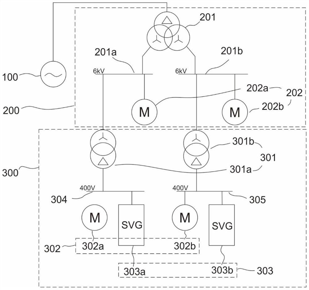
[0030] refer to figure 1 , which is the first embodiment of the present invention, provides a method and system for increasing the phase advance depth of a generator. The system includes a generator 100, a high-voltage plant assembly 200 and a low-voltage plant assembly 300, wherein the generator 100; The high-voltage plant assembly 200 is connected to the generator 100, including a three-phase split transformer 201, and a plant high-voltage auxiliary machine 202 connected to the three-phase split transformer 201; and, the low-voltage plant assembly 300 is connected to the high-voltage The plant components 200 are connected, including a double-winding step-down transformer 301 connected to the high-voltage plant component 200 , a plant low-voltage auxiliary machine 302 and a reactive power compensation device 303 connected to the double-winding step-down transformer 301 .

[0031] Among them, the generator 100 provides energy supply for the system, the high-voltage plant compo...

Embodiment 2

[0033] refer to Figure 1~2 , is the second embodiment of the present invention, which is different from the first embodiment in that: the output port of the generator 100 is connected to the three-phase split transformer 201 . The two output ports of the three-phase split transformer 201 are connected to the high-voltage bus A section 201a and the high-voltage bus B section 201b respectively, except for the connection with the generator 100. The high-voltage busbar A section 201a and the high-voltage busbar B section 201b are 6kV industrial busbars, and the industrial high-voltage auxiliary equipment 202 includes a first industrial high-voltage auxiliary equipment 202a and a second industrial high-voltage auxiliary equipment 202b. The plant high-voltage auxiliary machine 202a and the second plant high-voltage auxiliary machine 202b are 6kV plant high-voltage auxiliary machines.

[0034]The first factory high-voltage auxiliary machine 202a is connected to the three-phase spli...


PUM


Abstract

The invention discloses a method and system for improving the in-phase depth of a generator. The system comprises the generator, a high-voltage factory assembly, and a low-voltage factory assembly, wherein the high-voltage factory assembly is connected with the generator and comprises a three-phase split transformer and a factory high-voltage auxiliary machine connected with the three-phase split transformer; and the low-voltage factory assembly is connected with the high-voltage factory assembly and comprises a double-winding step-down transformer connected with the high-voltage factory assembly, and a factory low-voltage auxiliary machine and a reactive power compensation device which are connected with the double-winding step-down transformer. The invention provides the method and system for improving the in-phase depth of the generator, aiming at the problem that the voltage of a 400V factory auxiliary machine is too low, and the 400V factory auxiliary machine can not work normally during an in-phase test, so that the in-phase depth of the generator for a power plant is not high, a dynamic reactive power compensation device is added in a 400V low-voltage factory bus of the power plant, and the dynamic reactive power compensation device can automatically adjust the inductive reactive power output according to the voltage drop amplitude to improve the in-phase depth of the power plant.

Description

technical field [0001] The invention relates to the technical field of the phase advance depth of a power plant, in particular to a method and system for increasing the phase advance depth of a generator. Background technique [0002] After the reform of my country's electric power system, power generation enterprises can only increase the benefits of power generation enterprises by reducing power generation costs, improving unit reliability, and improving unit competitiveness. [0003] In recent years, when the power grid is running at low load, the problem of high voltage has become more and more prominent, and it is urgent for the unit to have a stronger phase advance capability. Compared with the actual phase advance capability of the unit during the low load period, the phase advance capability obtained by the phase advance test of most units is conservative, and has the potential to tap the phase advance capability. One of the important indicators that affects the pha...

Claims


Application Information

Patent Timeline
Patent Type & Authority Applications(China)
IPC IPC(8): H02J3/18
CPCH02J3/1885Y02E40/30
Inventor 蔡琼锋黄修喜刘德干黄文斐陈贞良莫树良陈振才叶俊锋柴琦
Owner HUANENG HAINAN POWER INC
Why Eureka
Try Eureka