Check patentability & draft patents in minutes with Patsnap Eureka AI!

A construction method for thermal insulation of thermally insulated pipe joints

A technology for pipe joints and construction methods, which is applied in the direction of protecting pipes, pipes/pipe joints/fittings, and pipe protection through heat insulation, and can solve the problems of reduced heat insulation performance of heat-insulated pipes, hidden dangers of sealing performance, and poor sealing of heat-insulated pipe joints. Achieve excellent mechanical and sealing properties, ensure integrity, excellent shrinkage properties and adhesive properties

Active Publication Date: 2015-10-21
BEIJING HTN PIPELINE EQUIP
View PDF7 Cites 0 Cited by
  • Summary
  • Abstract
  • Description
  • Claims
  • Application Information

AI Technical Summary

Problems solved by technology

[0008] Therefore, the technical problem to be solved by the present invention is to overcome the problem that the thermal insulation construction method of the thermal insulation pipeline joint in the prior art makes the sealing performance of the thermal insulation pipeline joint poor during construction, which leads to the decrease of the thermal insulation performance of the thermal insulation pipeline, and at the same time overcomes the need in the prior art. Holes are opened on the sleeve or sleeve, and there is a problem of hidden sealing performance at the opening, so as to provide a construction method for heat-insulating pipe joints with good sealing performance, no need to open holes on the sleeve in advance, and excellent thermal insulation performance

Method used


Image

  • A construction method for thermal insulation of thermally insulated pipe joints
  • A construction method for thermal insulation of thermally insulated pipe joints
  • A construction method for thermal insulation of thermally insulated pipe joints

Examples


Embodiment 1

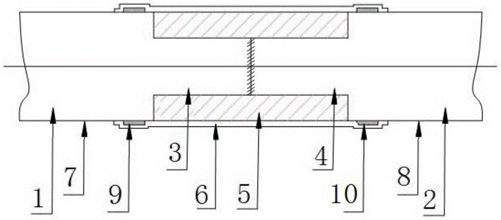
[0052] This embodiment provides a new construction method for insulation of heat-insulated pipe joints, including

[0053] A. The step of joining the exposed ports of the working pipes 3, 4 of the adjacent two sections of heat-insulated pipelines 1, 2 to form an interface area;

[0054] B. The step of forming the thermal insulation layer 5 by foaming on-site with a mold in the interface area;

[0055] C. The step of forming an outer sheath on the outer wall of the heat insulation layer 5 and part of the outer walls of the outer sheath pipes 7, 8 of the adjacent two sections of heat insulation pipelines 1, 2, in the step of forming the outer sheath, first Install sealing strips 9, 10 in the installation area adjacent to the outer walls of the outer protective tubes 7, 8, and then set a heat-shrinkable sleeve 6 on the outer wall of the heat-insulating layer 5 as an outer sheath, and the heat-shrinkable The two ends of the sleeve 6 are respectively overlapped on the installation...

Embodiment 2

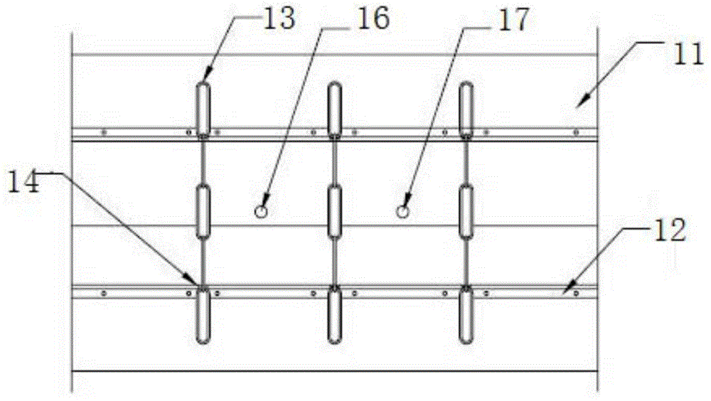
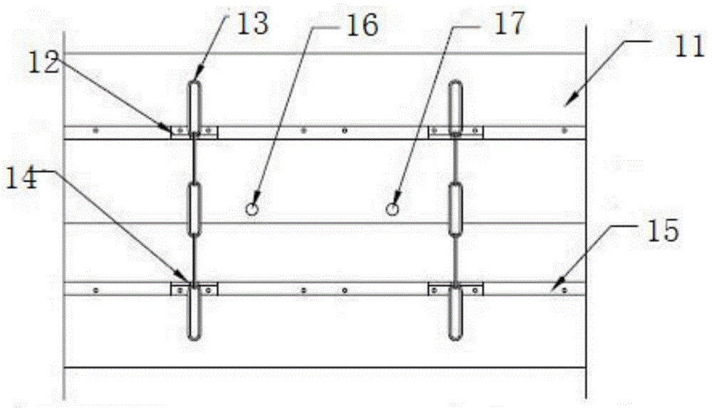
[0066] This embodiment provides a construction method for thermal insulation of heat-insulated pipe joints, which is a further improvement on the basis of Embodiment 1. In this embodiment, in the step of foaming to form the polyurethane foam layer, a portable Joint foaming molds, such as figure 2 As shown, the foaming mold includes a coiled plate 11 that can be rolled into a cylindrical shape, and a locking device located on the outer wall of the rolled plate 11 to lock the rolled plate 11 into a cylindrical shape. Before foaming, the two ends of the rolled board 11 are curled into a cylindrical shape according to the diameter of the pre-foamed polyurethane foam layer, and then the rolled board 11 is locked in the cylindrical shape with a locking device. The coiled plate 11 can be rolled into various cylindrical shapes with different inner diameters according to the different outer diameters of the heat insulating tubes within the allowable range of the length of the rolled p...

Embodiment 3

[0074] This embodiment provides a construction method for thermal insulation of heat-insulated pipe joints, which is a deformation on the basis of Embodiment 1. In this embodiment, after the formation of the thermal insulation layer 5 during the construction process, A plastic film is attached to the outer wall of 5 as a barrier layer, and the barrier layer is located between the outer wall of the heat-insulating layer 5 and the inner wall of the heat-shrinkable sleeve 6 to prevent the heat-shrinkable sleeve 6 from The inner gas in the thermal insulation layer 5 and / or the gas and moisture in the external environment are a barrier layer for the circulation of the heat-shrinkable sleeve 6 .

[0075] During the use of the heat-insulating pipe joint, when the gas or moisture in the external environment penetrates into the barrier layer through the tube wall of the heat-shrinkable sleeve 6, it is blocked by the barrier layer, so that the gas or moisture in the external environment ...


PUM

PropertyMeasurementUnit
lengthaaaaaaaaaa
lengthaaaaaaaaaa
thicknessaaaaaaaaaa

Abstract

The invention provides a construction method for thermal insulation of a thermal insulation pipeline joint. In the step of forming an outer protection layer, sealing rubber strips are installed in an installation area of the outer walls of adjacent outer protection pipes first, then, the outer wall of a thermal insulation layer is sleeved with a thermal contraction sleeve as the outer protection layer, the two ends of the thermal contraction sleeve are connected to the installation area of the adjacent outer protection pipes in an overlapped mode respectively and just cover the installation area, after the overlapped connection, the sealing rubber strips are away from the end portion of the thermal contraction sleeve for a certain distance, and finally the thermal contraction sleeve is heated, so that in the contraction process of the thermal contraction sleeve, the end portion of the thermal contraction sleeve and the end portions of the outer protection pipes are sealed by the sealing rubber strips in a fused mode. Because the sealing rubber strips are arranged in the installation area and are away from the end portion of the thermal contraction sleeve for a certain distance, it can be guaranteed that when the thermal contraction sleeve contracts, the sealing rubber strips in the fused state can be fused and overflow to the edge of the installation area, and thus the end portion of the thermal contraction sleeve and the end portions of the adjacent outer protection pipes can be connected in the sealed mode by the fused sealing rubber strips.

Description

technical field [0001] The invention relates to a novel heat-insulating construction method for heat-insulating pipe joints, and belongs to the technical field of heat-insulating heat-insulating pipe joints for medium transport. Background technique [0002] In the fields of central heating, cooling, oil and gas, etc., the pipelines used for medium transportation need to be insulated to ensure the insulation performance of the pipelines during the medium transportation process. Insulated pipes are generally prefabricated in the factory according to the length, and then installed on site to form joints at the joints of two insulated pipes. In the entire insulated pipe network, the quality of the joint installation will have a greater impact on the service life of the entire pipe network. Impact. [0003] In the prior art, the construction methods for thermal insulation treatment of thermal insulation pipeline joints mainly include the following two types: [0004] 1. Use he...

Claims


Application Information

Patent Timeline
Patent Type & Authority Patents(China)
IPC IPC(8): F16L59/18F16L59/02B29C44/02B29C63/42
CPCB29C44/02B29C63/42F16L59/028F16L59/182
Inventor 叶勇周抗冰张红莲周莹莹
Owner BEIJING HTN PIPELINE EQUIP
Features
  • R&D
  • Intellectual Property
  • Life Sciences
  • Materials
  • Tech Scout
  • Unparalleled Data Quality
  • Higher Quality Content
  • 60% Fewer Hallucinations
Learn More