LED fluorescent tube with modified structure

A LED fluorescent lamp, improved structure technology, applied in the direction of light source, electric light source, slender light source, etc., can solve the problems of local high temperature of the lamp tube, difficulty in meeting the requirements of safety regulations and electromagnetic compatibility of the driving power supply, high maintenance cost, etc. low effect

Inactive Publication Date: 2014-02-12
姚志峰
View PDF0 Cites 15 Cited by
  • Summary
  • Abstract
  • Description
  • Claims
  • Application Information

AI Technical Summary

Problems solved by technology

However, the existing electronic components of the driving power supply are mainly concentrated together, and local high temperature of the lamp tube is likely to occur during operation, which affects the service life of the lamp tube. Although the driving power supply has the advantage of adapting to a wide voltage range, the maintenance of the driving power supply is inconvenient and expensive. High, and once the driving power is damaged, the whole lamp will not work. If the LED in the lamp is damaged and causes no load, the driving power will also be damaged for a long time, and many current driving power are difficult to comply with safety regulations and electromagnetic compatibility. requirements, it is easy to cause interference to electrical appliances in the surrounding range during use

Method used


Image

  • LED fluorescent tube with modified structure
  • LED fluorescent tube with modified structure
  • LED fluorescent tube with modified structure

Examples


Embodiment Construction

[0028] The present invention will be further described below in conjunction with the accompanying drawings and specific embodiments.

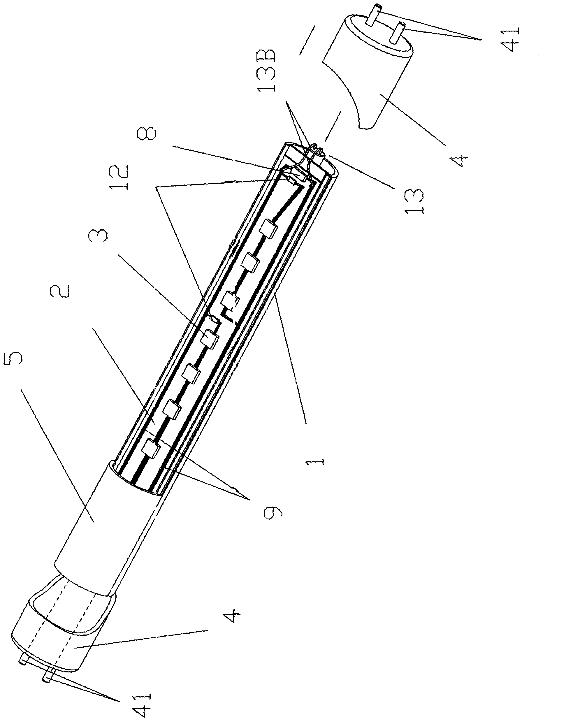
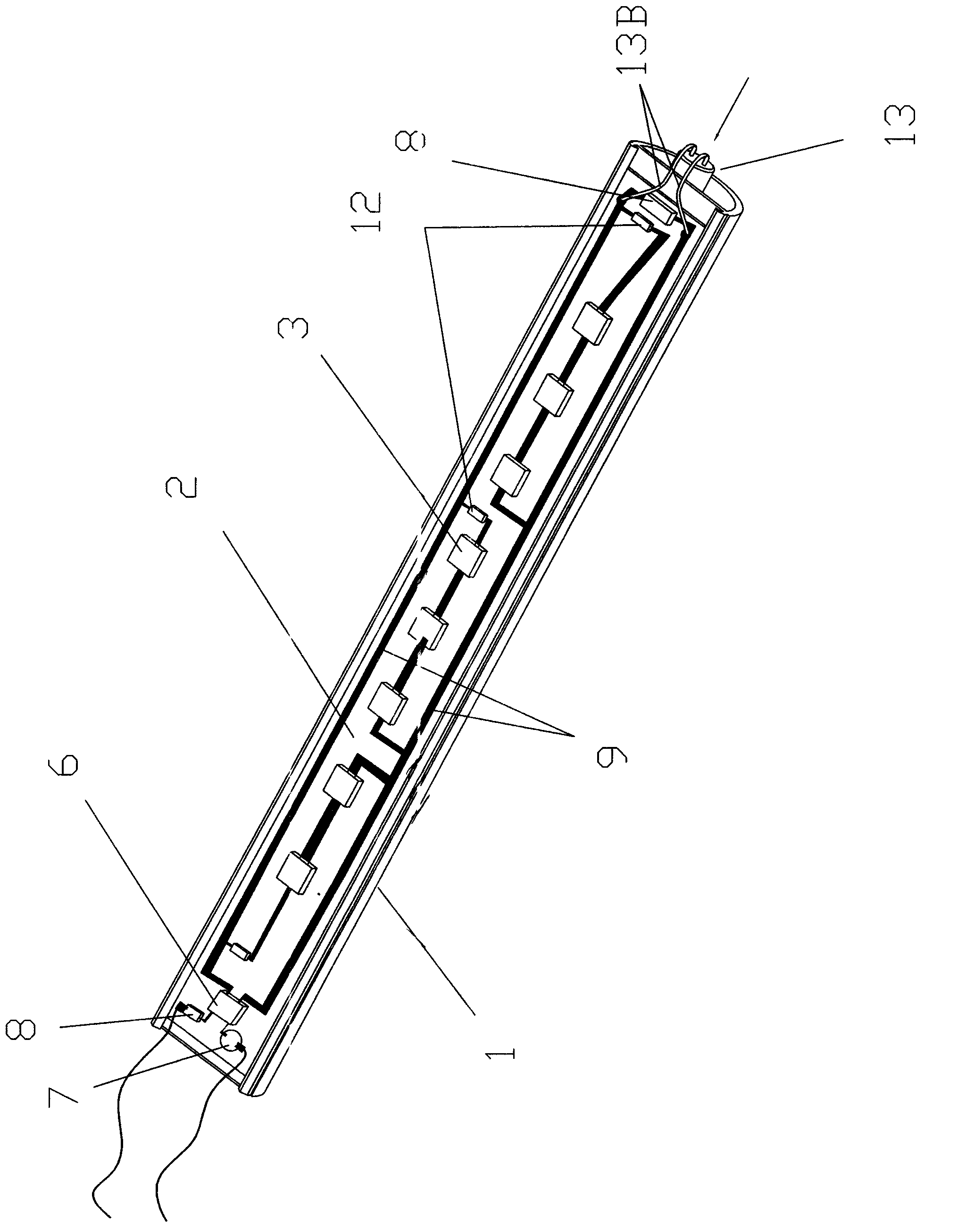
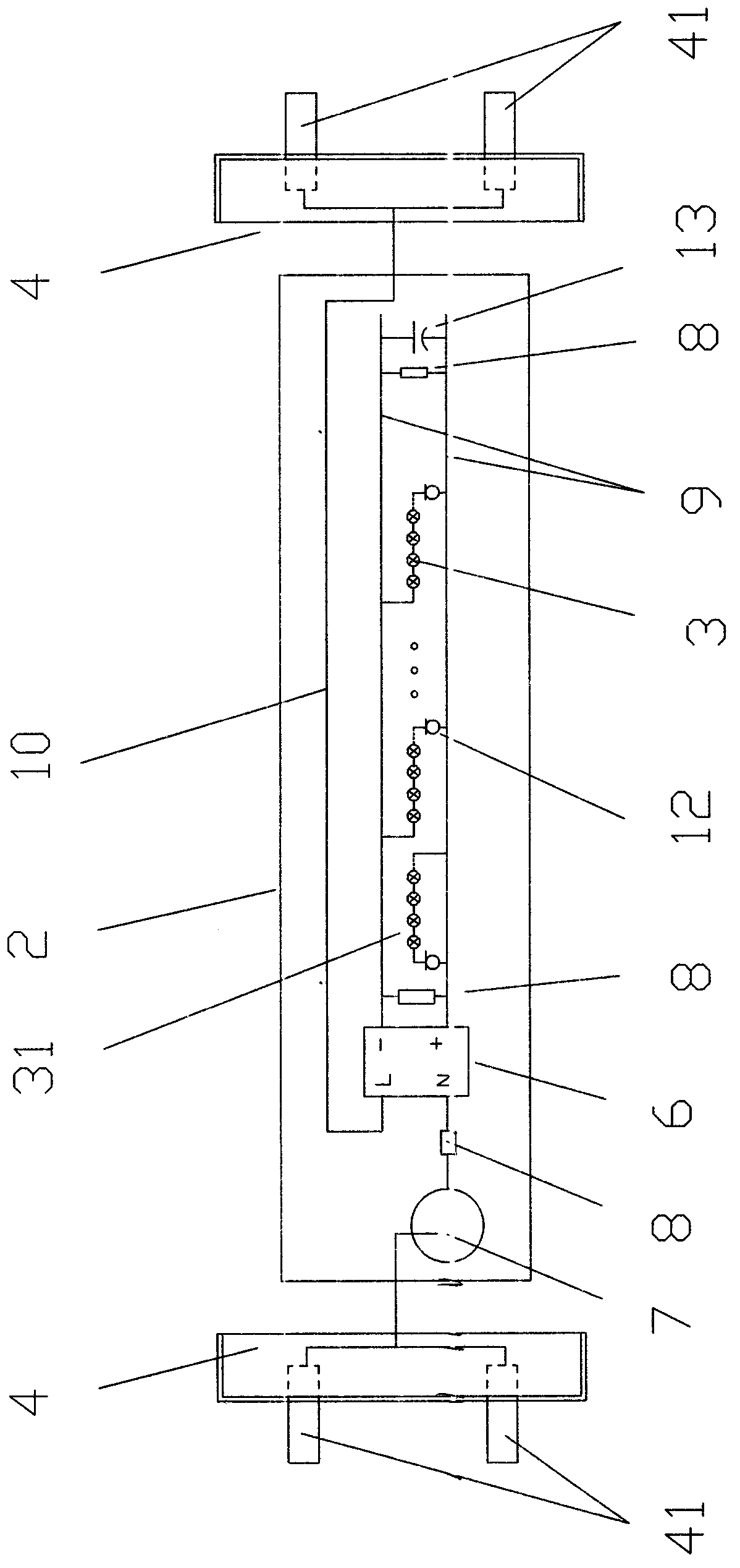
[0029] refer to Figure 1 to Figure 41. An improved structure of the LED fluorescent tube structure of the present invention comprises: a light tube base 1, a plastic cover 5 arranged on the lamp base, a strip-shaped PCB board 2, and the width of the strip-shaped PCB board 2 is 5 to 30 mm, the strip-shaped PCB board 2 can be a PCB board with a single-sided cloth conductive circuit layer, because the light pipe base 1 can be made of aluminum alloy material, the bottom surface of the PCB board 2 is close to the top surface of the light pipe base 1, and is arranged on The end caps 4 at both ends of the base and the casing, at least one end cap at the two ends is provided with a conductive column 41 connected to the power supply and the conductive circuit layer of the PCB board, and at least one rectifier bridge stack 6 is provided on at least one ...


PUM


Abstract

The invention discloses an LED fluorescent tube with a modified structure. The LED fluorescent tube comprises a lamp tube base, and a plastic housing, a PCB board, an LED illuminant and an end cover which are arranged on the lamp tube base, wherein at least one bridge rectifier and at least one resistor are arranged on the surface of at least one end of the PCB board, at least one capacitor is arranged on the surface of the other end, at least one resistor or constant current diode which is connected with two conductive pins of the capacitor in parallel is arranged between the two conductive pins of the capacitor, the bridge rectifier and the resistor are arranged between an LED on the tail end and the end face of a PCB, the capacitor and the resistor or the constant current diode are arranged between the LED on the other end of the surface of the PCB board and the end face of the PCB, the anodes and the cathodes of the two conductive pins of the capacitor are respectively electrically connected with conductive circuit layers which are arranged on two sides of the LED along a longitudinal direction and are provided with anodes and cathodes, and a plurality of LED lamp string groups are arranged between the conductive circuit layers provided with the anodes and the cathodes. The LED fluorescent tube has the advantages of low cost, high efficiency, safety, long service life, convenience for maintenance and low cost.

Description

Technical field [0001] The invention relates to an illuminating device, in particular to an LED fluorescent tube with an improved structure. Background technique [0002] At present, the use of LED for lighting has become a trend. LED has the advantages of high efficiency, energy saving and low working voltage. It consists of shell, LED, and driving power supply. However, the existing electronic components of the driving power supply are mainly concentrated together, and local high temperature of the lamp tube is likely to occur during operation, which affects the service life of the lamp tube. Although the driving power supply has the advantage of adapting to a wide voltage range, the maintenance of the driving power supply is inconvenient and expensive. High, and once the driving power is damaged, the whole lamp will not work. If the LED in the lamp is damaged and causes no load, the driving power will also be damaged for a long time, and many current driving power are di...

Claims


Application Information

Patent Timeline
Patent Type & Authority Applications(China)
IPC IPC(8): F21S2/00F21V23/02F21V23/06F21V29/00F21Y101/02F21K9/27F21V29/10F21Y103/10F21Y115/10
Inventor 姚志峰
Owner 姚志峰
Why Eureka
Try Eureka