Two-stage flash evaporator of waste heat power generation system of cement kiln

A technology of waste heat power generation and two-stage flash evaporation, which is used in waste heat treatment, steam generation, steam engine installations, etc., can solve the problems of excess, the heat source cannot be fully utilized, and the economic benefits of waste heat recovery cannot be guaranteed, so as to improve heat utilization. High efficiency, simple system and easy operation

Inactive Publication Date: 2014-02-12
娄卡奔新能源科技发展(上海)有限公司
View PDF0 Cites 3 Cited by
  • Summary
  • Abstract
  • Description
  • Claims
  • Application Information

AI Technical Summary

Problems solved by technology

Moreover, the fluctuation range often exceeds the self-adjusting range of conventional waste heat power generation system design, making the waste heat power generation system unable to operate stably
Some fluctuations are even so large that the usual waste heat power generation system is forced to disconnect and shut down, and the economic benefits of waste heat recovery cannot be guaranteed
At present, although some cement plants have introduced waste heat power generation systems with flash evaporators, which have the ability to actively adjust and resolve the influence of process flue gas instability, there are obvious defects because most of these cement plants use single-stage flash evaporators. The steam waste heat power generation system cannot adapt to the large-scale flue gas fluctuations of the cement kiln, and cannot guarantee the stable operation of waste heat power generation. Moreover, the temperature of the hot water discharged from the outlet of the flash evaporator is still high, and the heat source has not been fully utilized.

Method used


Image

  • Two-stage flash evaporator of waste heat power generation system of cement kiln
  • Two-stage flash evaporator of waste heat power generation system of cement kiln

Examples


Embodiment Construction

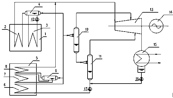
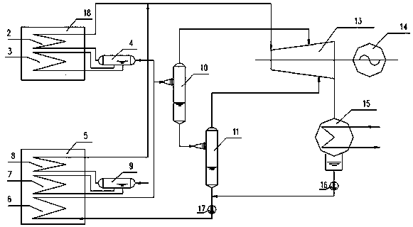
[0017] exist figure 1 with figure 2 In the two-stage flash evaporator described in the present invention, the two flash evaporators are connected in series, the economizer 6 is connected to the water inlet of the primary flash evaporator 10 through a pipeline, and the water outlet of the primary flash evaporator 10 is connected to the secondary flash evaporator The water inlets of 11 are connected, the water outlet of the secondary flash evaporator 11 is connected to the boiler feed water pump 17, and the steam outlets of the primary flash evaporator 10 and the secondary flash evaporator 11 respectively lead to the rear stage of the steam turbine 13 to perform work.

[0018] During work, the high-temperature water heated by the economizer 6 is sent to the AQC furnace drum 5, the PH furnace drum 4 (or the SP furnace drum 18) and the first-stage flash evaporator 10 respectively. The high-temperature water entering the primary flash evaporator 10 generates saturated steam under...


PUM


Abstract

The invention relates to a two-stage flash evaporator of a waste heat power generation system of a cement kiln The waste gas utilization efficiency of the cement kiln can be particularly improved during waste heat power generation by the aid of the two-stage flash evaporator. The two-stage flash evaporator is characterized in that two flash evaporators are serially connected with each other, a coal economizer is connected with a water inlet of the primary flash evaporator by a pipeline, a water outlet of the primary flash evaporator is connected with a water inlet of the secondary flash economizer, a water outlet of the secondary flash evaporator is connected to a boiler feed water pump, and a steam outlet of the primary flash evaporator and a steam outlet of the secondary flash evaporator are respectively communicated with a rear stage of a steam turbine to do work. The two-stage flash evaporator has the advantages that a system is simple and is low in cost, convenient to operate and adaptive to the characteristic of sharp fluctuation of waste gas parameters of the cement kiln, maximum generated power can be acquired from low-grade heat sources, the exhaust temperature of a boiler can be about 90 DEG C under the control, the heat utilization rate of low-temperature flue gas can be increased, and accordingly the purpose of utilizing energy to the greatest extent can be achieved.

Description

technical field [0001] The invention relates to a two-stage flash evaporator in a cement kiln waste heat power generation system, in particular to a two-stage flash evaporator capable of improving the utilization efficiency of waste gas in the cement kiln waste heat power generation system. Background technique [0002] As we all know, saving energy is an established long-term policy of our country, among which the utilization of waste heat is the most active and effective means. In many fields of existing industries in our country, the utilization of waste heat in the production process has attracted attention. In recent years, a large number of new process equipment and production lines have been invested in the transformation of the cement industry, and it is equipped with a pure medium and low temperature cement waste heat power generation system. In practical applications, due to the characteristics of the process, most of the parameters of the process waste heat flue g...

Claims


Application Information

Patent Timeline
IPC IPC(8): F22B3/04F27D17/00F01K11/02
CPCY02P10/25
Inventor 叶金辉
Owner 娄卡奔新能源科技发展(上海)有限公司
Why Eureka
Try Eureka