Device and method for measuring relative intensity noise of laser

A technology of relative intensity noise and measurement method, which is applied in the direction of testing optical performance, etc., can solve the problems of lower measurement accuracy, large external interference, and large limitations, and achieve the effect of improving measurement accuracy and breaking through limitations

Active Publication Date: 2014-02-12
广东国天时空科技有限公司
View PDF11 Cites 11 Cited by
  • Summary
  • Abstract
  • Description
  • Claims
  • Application Information

AI Technical Summary

Problems solved by technology

The traditional solution needs to directly inject the output optical power of the laser into the photodetector. When the output optical power is large, it will obviously exceed the saturated input optical power of the detector, resulting in errors in the conversion of electro-optical noise, and may even exceed the detector’s maximum Input optical power, causing damage to the detector
[0013]2. Near DC noise is relatively large, which affects RIN measurement accuracy
For electronic devices, the frequency spect...

Method used


Image

  • Device and method for measuring relative intensity noise of laser
  • Device and method for measuring relative intensity noise of laser
  • Device and method for measuring relative intensity noise of laser

Examples


Embodiment Construction

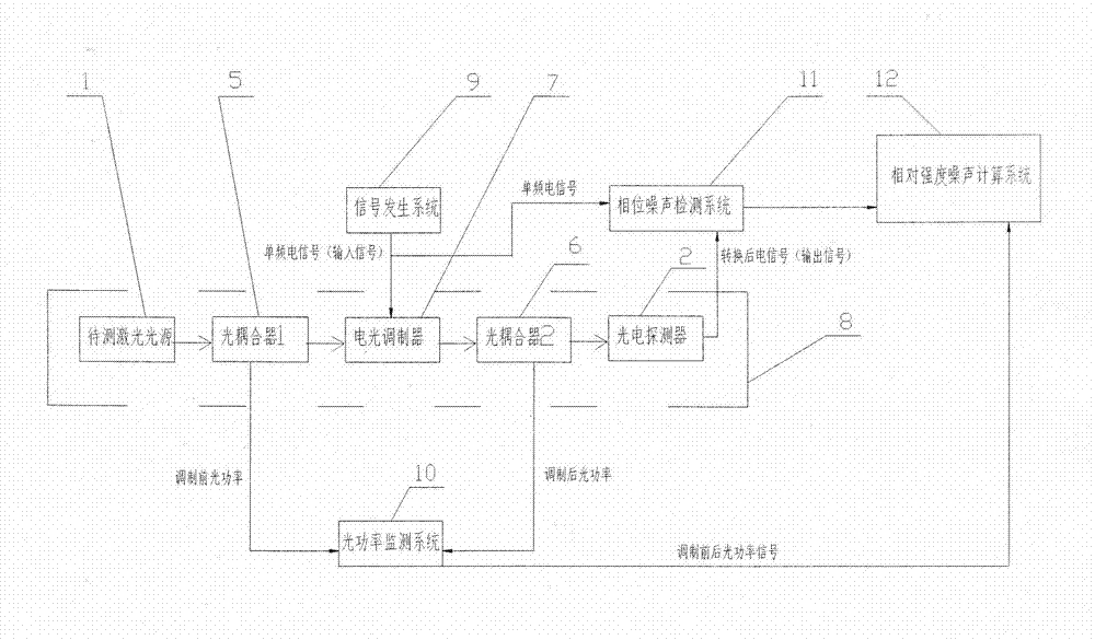
[0034] like figure 2As shown, a measurement device for relative intensity noise of a laser is composed of a microwave photon link 8, a signal generation system 9, an optical power monitoring system 10, a phase noise detection system 11, and a relative intensity noise calculation system 12. The microwave photon link Circuit 8 includes a laser to be tested 1, a photodetector 2, an optical coupler I5, an optical coupler II6, and an electro-optical modulator 7. The microwave photon link 8 is an intensity modulation-direct demodulation link, or a phase modulation-coherent link. Demodulation link; the signal generating system 9 includes a signal generating device capable of generating single-frequency electrical signals; the optical power monitoring system 10 includes an optical power device; the output optical signal of the laser to be tested 1 is input through the optical coupler I5 To the electro-optic modulator 7, the single-frequency electrical signal generated by the signal g...


PUM


Abstract

The invention discloses a device and method for measuring relative intensity noise of a laser. According to the method for measuring the relative intensity noise of the laser, the principle that after a single frequency point electric signal passes through a microwave photon link, a phase-noise index is correspondingly deteriorated is adopted and the relative intensity noise of the laser in the link is calculated through the change quantity of phase noise. The basic structure of the device for measuring the relative intensity noise of the laser comprises a single frequency point signal resource, a microwave photon link, an optical power meter and a phase-noise detector, wherein the microwave photon link is mainly composed of the laser, an electro-optical modulator, an optical coupler and a photoelectric defector. Compared with a traditional measuring method, the method for measuring the relative intensity noise of the laser has the advantages that the measuring process is conducted on the high-frequency end of an electricity domain, influence caused by various environment noises near the direct current end is avoided, the measuring accuracy is improved, the output power of the laser to be detected does not need to be considered according to the scheme, and the limitation, caused by optical output power, of a measuring system in the traditional measuring method is overcome.

Description

technical field [0001] The invention belongs to the field of electronic measurement, in particular to a measuring device and method for the relative intensity noise of a laser. Background technique [0002] Optoelectronic technology is an important part of contemporary high-tech, and plays a pivotal role in national economy and national defense construction. With the rapid development of optoelectronic technology, lasers, as an important optoelectronic component, have been widely used in many fields such as optical communication, information storage, medical treatment, and optical sensing. In the fields of optical storage and optical communication, the relative intensity noise (Relative Intensity Noise, hereinafter referred to as RIN) of the laser is one of the important parameters to determine the performance index of the system. The RIN of the laser will affect the signal-to-noise ratio and sensitivity of the communication system. [0003] The relative intensity noise of ...

Claims


Application Information

Patent Timeline
IPC IPC(8): G01M11/02
Inventor 洪俊雷军宋绍民王勇刚方小勇
Owner 广东国天时空科技有限公司
Why Eureka
Try Eureka