W-type common-path time modulation interference spectrum imaging device and method
A technology of interferometric spectral imaging and time modulation, applied in the optical field, can solve problems such as poor stability, and achieve the effects of strong anti-interference ability, low stray light, and high flux
- Summary
- Abstract
- Description
- Claims
- Application Information
AI Technical Summary
Problems solved by technology
Method used
Image
Examples
Embodiment 1
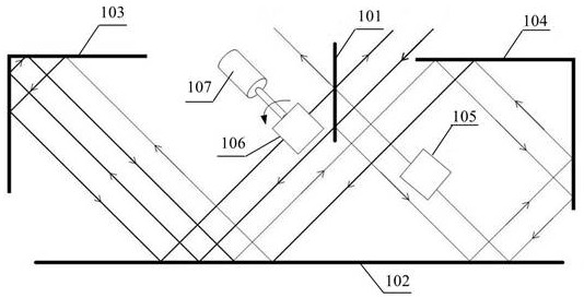
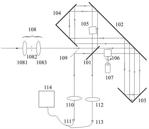
[0044] Embodiment 1 provides a W-type common optical path time modulation interference spectroscopy imaging device, see figure 1 , figure 2 , including: a W-type common optical path interferometer, a pre-assembly 108 , a convergence assembly, a detection and acquisition module and a signal processing module 114 .
[0045] Wherein, the W-type common optical path interferometer includes a beam splitter 101 , a first plane mirror 102 , a first corner mirror 103 , a second corner mirror 104 , and a first optical path adjustment component (including a first prism 105 ) and a second optical path adjustment assembly (including a second prism 106 and a motor 107, the motor 107 drives the second prism 106 to rotate). That is, both the first reflecting element and the second reflecting element are corner reflectors.
[0046] The front assembly 108 includes a condensing lens 1081, a diaphragm 1082 and a collimating lens 1083 which are arranged in sequence along the optical path. The ...
Embodiment 2
[0071] Embodiment 2 provides a W-type common optical path time modulation interference spectroscopy imaging method, which is implemented by using a W-type common optical path time modulation interference spectroscopy imaging device provided in Embodiment 1, and the W-type common optical path interferometer is set to a common optical path and Asymmetric structure, by arranging a moving mirror scanning mechanism in the W-type common optical path interferometer for generating a time-varying optical path difference, the working mode of the W-type common optical path time modulation interference spectroscopy imaging device is time Modulation working mode.
[0072] A specific method corresponding to the apparatus of Embodiment 1 is provided below.
[0073] A W-type common optical path time modulation interference spectroscopy imaging method, see figure 2 , including the following steps:
[0074] Step 1. The target light becomes parallel light after passing through the front assem...
Embodiment 3
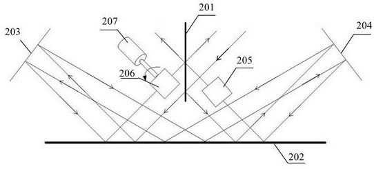
[0083] Embodiment 3 provides a W-type common optical path time modulation interference spectroscopy imaging device, which is different from Embodiment 1 in that the first reflection element and the second reflection element are both flat reflection mirrors.
[0084] Specifically, see image 3 , Figure 4 , Embodiment 3 provides a W-type common optical path time modulation interference spectroscopy imaging device including a W-type common optical path interferometer, a pre-assembly 208 , a convergence assembly, a detection and acquisition module and a signal processing module 214 .
[0085] The W-type common optical path interferometer includes a beam splitter 201 , a first plane mirror 202 , a second plane mirror 203 , a third plane mirror 204 , and a first optical path adjustment component (including a first prism 205 ) and a second optical path adjustment assembly (including a second prism 206 and a motor 207 ). The front assembly 208 includes a condensing lens 2081 , a di...
PUM
 Abstract
Description
Claims
Application Information
 - R&D
- Intellectual Property
- Life Sciences
- Materials
- Tech Scout
- Unparalleled Data Quality
- Higher Quality Content
- 60% Fewer Hallucinations
Browse by: Latest US Patents, China's latest patents, Technical Efficacy Thesaurus, Application Domain, Technology Topic, Popular Technical Reports.
© 2025 PatSnap. All rights reserved.Legal|Privacy policy|Modern Slavery Act Transparency Statement|Sitemap|About US| Contact US: help@patsnap.com


