
A real-time detection system and method for fuel cell internal performance

A fuel cell, real-time detection technology, applied in the direction of measuring electricity, measuring devices, measuring electrical variables, etc., can solve the problems of insufficient data, limited reference value, and no use of drawing two-dimensional images, etc., to achieve fewer system components and improve reliability performance, easy connection

Active Publication Date: 2016-06-22
TONGJI UNIV
View PDF6 Cites 0 Cited by
  • Summary
  • Abstract
  • Description
  • Claims
  • Application Information

AI Technical Summary

Problems solved by technology

[0004] In view of the fact that most of the existing methods can only measure the overall output performance of the fuel cell power supply, it is impossible to know the real-time internal current density distribution and temperature distribution, and the reference value is limited
However, the detection of the current density distribution and temperature distribution of the internal partitions of the fuel cell is still a field that is rarely involved. Even if the "Fuel Cell Internal Current Density Distribution Measurement Gasket" (Patent No.: CN200510041871.9) invented by Guo Liejin et al. The partition current is led to the external circuit through the ribs of the current density distribution measuring gasket that completely coincides with the ribs of the flow field plate, and then measured. This method can only obtain the one-dimensional comprehensive current distribution inside the fuel cell. The obtained data It is not comprehensive enough and does not use the method of drawing two-dimensional images, so it cannot intuitively and real-time display the two-dimensional current density distribution and temperature distribution inside the fuel cell, and it is not easy to understand and examine some regular characteristics of the fuel cell

Method used


Image

  • A real-time detection system and method for fuel cell internal performance
  • A real-time detection system and method for fuel cell internal performance
  • A real-time detection system and method for fuel cell internal performance

Examples


Embodiment 1

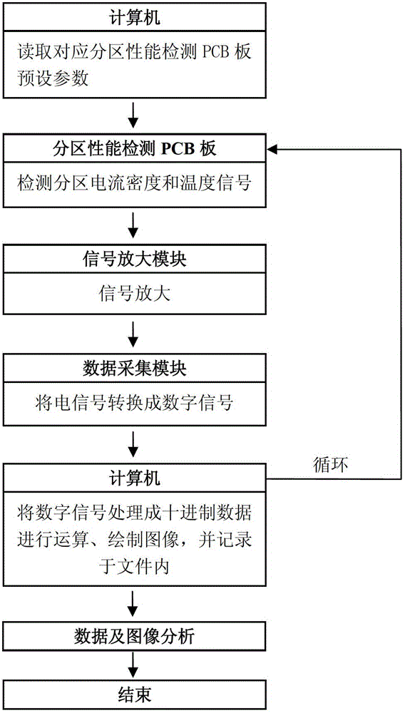
[0030] Such as figure 1 As shown, a real-time detection system for the internal performance of a fuel cell includes a partition performance detection PCB board 1, a signal amplification module 2, a data acquisition module 3, a universal interface bus 4 and a computer 5, a partition performance detection PCB board 1, a signal amplification module 2 It is connected to the data acquisition module 3 in sequence, and the data acquisition module 3 is connected to the computer 5 through the universal interface bus 4.

[0031] Among them, the partition performance detection PCB board 1 is set inside the fuel cell and closely adheres to the reaction layer inside the fuel cell. The partition performance detection PCB board 1 uses multilayer printing technology to divide multiple independent detection partitions. Each detection partition There are current sensing resistors and temperature sensing resistors inside, and signals are generated according to the potential difference between the tw...


PUM


Abstract

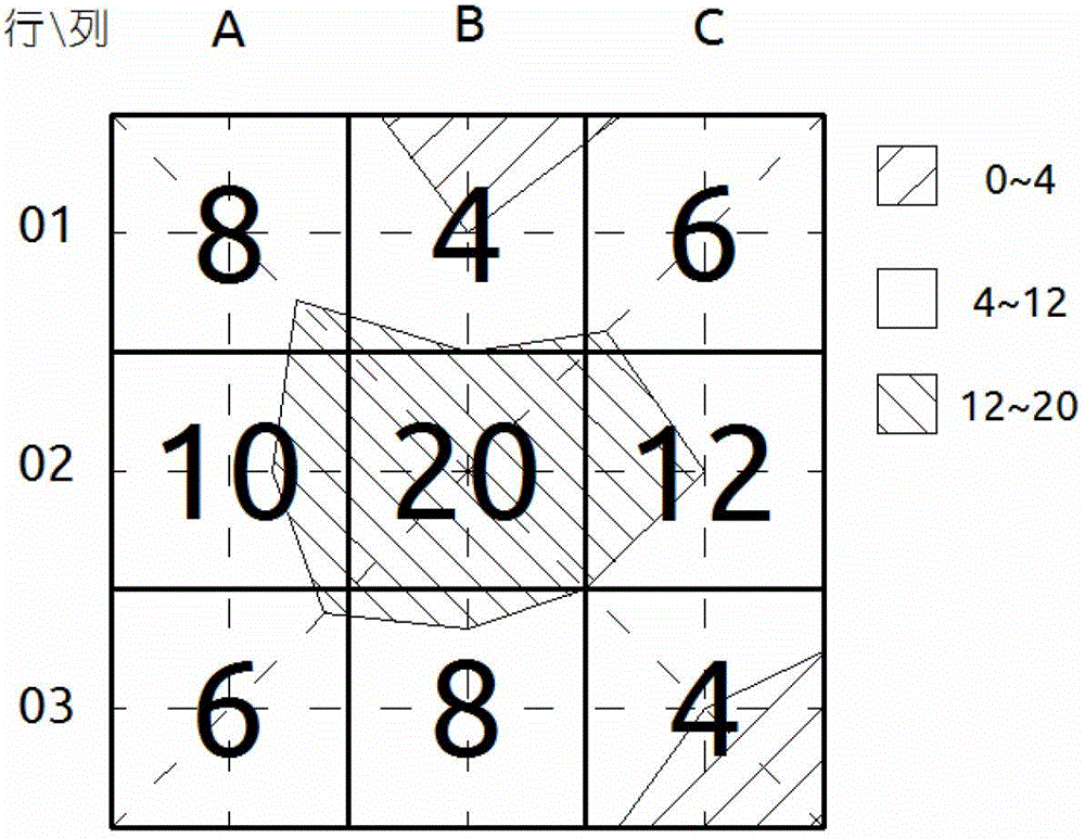
The invention relates to a fuel cell detection system and method. The system includes a computer, a partition performance detection PCB board, a signal amplification module, a data acquisition module and a general interface bus. The computer detects, calculates and records the partition performance detection PCB board through the general interface bus. The measured data is processed into a two-dimensional distribution image according to the algorithm. Compared with the prior art, the present invention establishes an in-situ diagnostic system for studying the non-uniform electrochemical reaction on the active region of the fuel cell membrane electrode, and realizes simultaneous measurement of the fuel cell current density and local temperature distribution without interfering with the reaction process , to overcome the traditional defects of no two-dimensional visualization image, for the fault diagnosis of each local area of ​​the fuel cell, to understand the dynamic response law and electrochemical reaction mechanism of the fuel cell, to study the durability, decay law and life prediction of the vehicle-mounted fuel cell. theoretical and practical value.

Description

Technical field [0001] The invention relates to a fuel cell detection system and method, in particular to a non-interference real-time detection system and method of the internal performance of a fuel cell. Background technique [0002] With the development of the fuel cell business and the advancement of its commercialization requirements, how to improve the life and reliability of fuel cells has become a major key that must be overcome. The life and performance of the proton exchange membrane are affected by many factors, and the influence of these factors is directly reflected in the current density and temperature distribution inside the fuel cell. The current density distribution is a comprehensive manifestation of the distribution of reactants, temperature and water in a proton exchange membrane fuel cell. The uneven distribution of current density in the active area will produce differences in internal voltage and in-plane current, resulting in a decrease in the utilizati...

Claims


Application Information

Patent Timeline
Patent Type & Authority Patents(China)
IPC IPC(8): G01R31/36
Inventor 林瑞俞佳伟唐文超张轶之曹春晖杨代军
Owner TONGJI UNIV
Learn More