
Multi-frequency circularly polarized antenna

A technology of circularly polarized antennas and antenna slices, applied to antenna unit combinations, antennas, and loop antennas with different polarization directions, can solve the problem that a single positioning system cannot provide positioning services, and achieve multi-system compatibility and low cost Low, simple structure effect

Inactive Publication Date: 2014-02-12
BEIJING UNIV OF POSTS & TELECOMM
View PDF1 Cites 3 Cited by
  • Summary
  • Abstract
  • Description
  • Claims
  • Application Information

AI Technical Summary

Problems solved by technology

With the increasing demand for satellite navigation and positioning, a single positioning system cannot provide more accurate positioning services

Method used


Image

  • Multi-frequency circularly polarized antenna
  • Multi-frequency circularly polarized antenna
  • Multi-frequency circularly polarized antenna

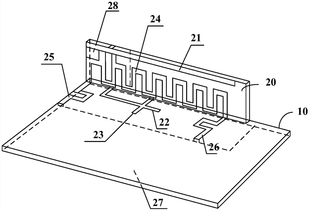
Examples


Embodiment Construction

[0023] In order to make the object, technical solution and advantages of the present invention clearer, the present invention will be further described in detail below with reference to the accompanying drawings and examples.

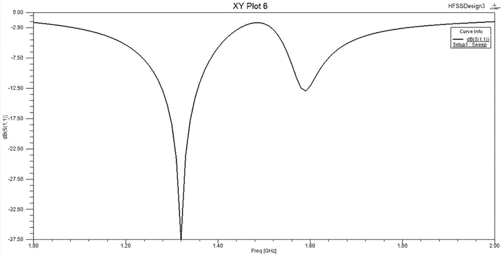
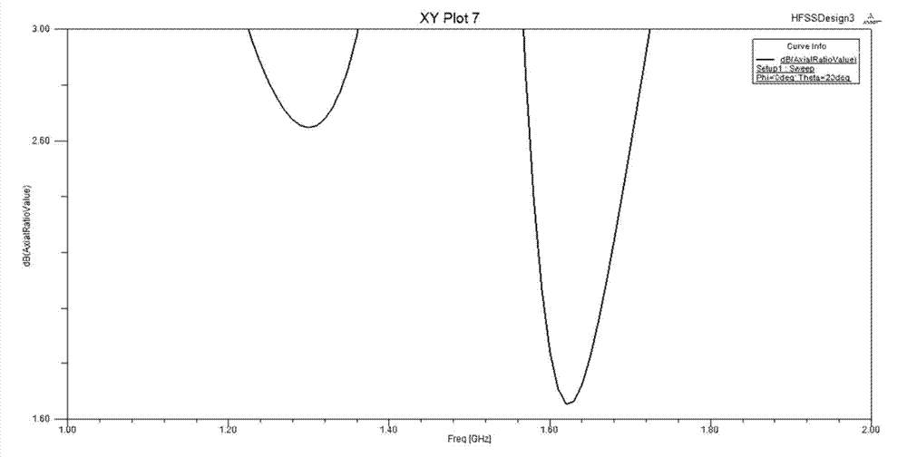
[0024] figure 1 It is a structural schematic diagram of the multi-frequency circularly polarized antenna of the present invention. like figure 1 As shown, a kind of multi-frequency circularly polarized antenna provided by the present invention includes: a rectangular dielectric plate 10 and an antenna piece 20, and the antenna piece 20 is arranged along one side of the rectangular dielectric plate 10 from the end corner of the rectangular dielectric plate 10 , the antenna piece 20 is perpendicular to the rectangular dielectric plate 10 . The shape and size of the rectangular dielectric plate 10 are the same as the device to which the antenna is applied. For example, if the antenna of the present invention is used in the navigation and positioning of a...


PUM


Abstract

The invention provides a multi-frequency circularly polarized antenna comprising a rectangular dielectric slab and an antenna sheet. The antenna sheet is arranged along one edge of the rectangular dielectric slab from one end corner of the rectangular dielectric slab, is perpendicular to the rectangular dielectric slab, and comprises three antenna branch sections and an annular structure, wherein the annular structure is connected with the three antenna branch sections and used for supplying power for the three antenna branch sections. The first antenna branch section and the second antenna branch section resonate at different working frequencies; the third antenna branch section is respectively perpendicular to the first antenna branch section and the second antenna branch section. The multi-frequency circularly polarized antenna can receive satellite signals of various frequency bands, and has the advantages of being small in size, simple in structure, low in manufacturing cost and the like.

Description

technical field [0001] The invention relates to the field of positioning antennas, in particular to a multi-frequency circularly polarized antenna. Background technique [0002] With the rapid development of wireless communication technology, the global satellite positioning system (GNSS) has been widely used in various fields. Among them, GPS (Global Positioning System) in the United States, GLONASS (Global Navigation Satellite System) in Russia, Galileo (Galileo Positioning System) in Europe and BDS (BeiDou Navigation Satellite System) in China system) is the main satellite positioning and navigation system in the world. GPS requires the receiving antenna to work with circular polarization in the three frequency bands of 1176.45MHz (L5), 1227.6MHz (L2 / L2C) and 1575.42 (L1 / L1C)MHz. The European Galileo system requires the antenna to work in the 1575.420MHz (E1), 1278.750MHz (E6), 1207.140MHz (E5b), 1191.795MHz (E5) and 1176.450MHz (E5a) frequency bands. With the increasi...

Claims


Application Information

Patent Timeline
Patent Type & Authority Applications(China)
IPC IPC(8): H01Q21/24H01Q21/30H01Q1/36H01Q7/00
Inventor 姚远张友博俞俊生陈晓东刘小明
Owner BEIJING UNIV OF POSTS & TELECOMM
Learn More