
Device for analyzing optical fiber path characteristics and method for analyzing same

一种特性分析、光线路的技术,应用在测量装置、光学仪器测试、测试光纤/光波导设备等方向,能够解决温度依赖性大、成本多、成本很难使用等问题,达到低成本的效果

Active Publication Date: 2014-02-12
NIPPON TELEGRAPH & TELEPHONE CORP
View PDF10 Cites 8 Cited by
  • Summary
  • Abstract
  • Description
  • Claims
  • Application Information

AI Technical Summary

Problems solved by technology

[0010] However, optical branching devices with wavelength routing functions, represented by arrayed waveguide diffraction grating wavelength division multiplexers, are usually very expensive, and it is difficult in terms of cost to accommodate a large number of access optical systems for joiners. used in
In addition, since such optical components are highly temperature-dependent and require an additional temperature adjustment function, the cost required for system construction becomes large.

Method used


Image

  • Device for analyzing optical fiber path characteristics and method for analyzing same
  • Device for analyzing optical fiber path characteristics and method for analyzing same
  • Device for analyzing optical fiber path characteristics and method for analyzing same

Examples


Embodiment Construction

[0060] Embodiments of the present invention will be described with reference to the drawings. The embodiments described below are examples of the configuration of the present invention, and the present invention is not limited to the following embodiments.

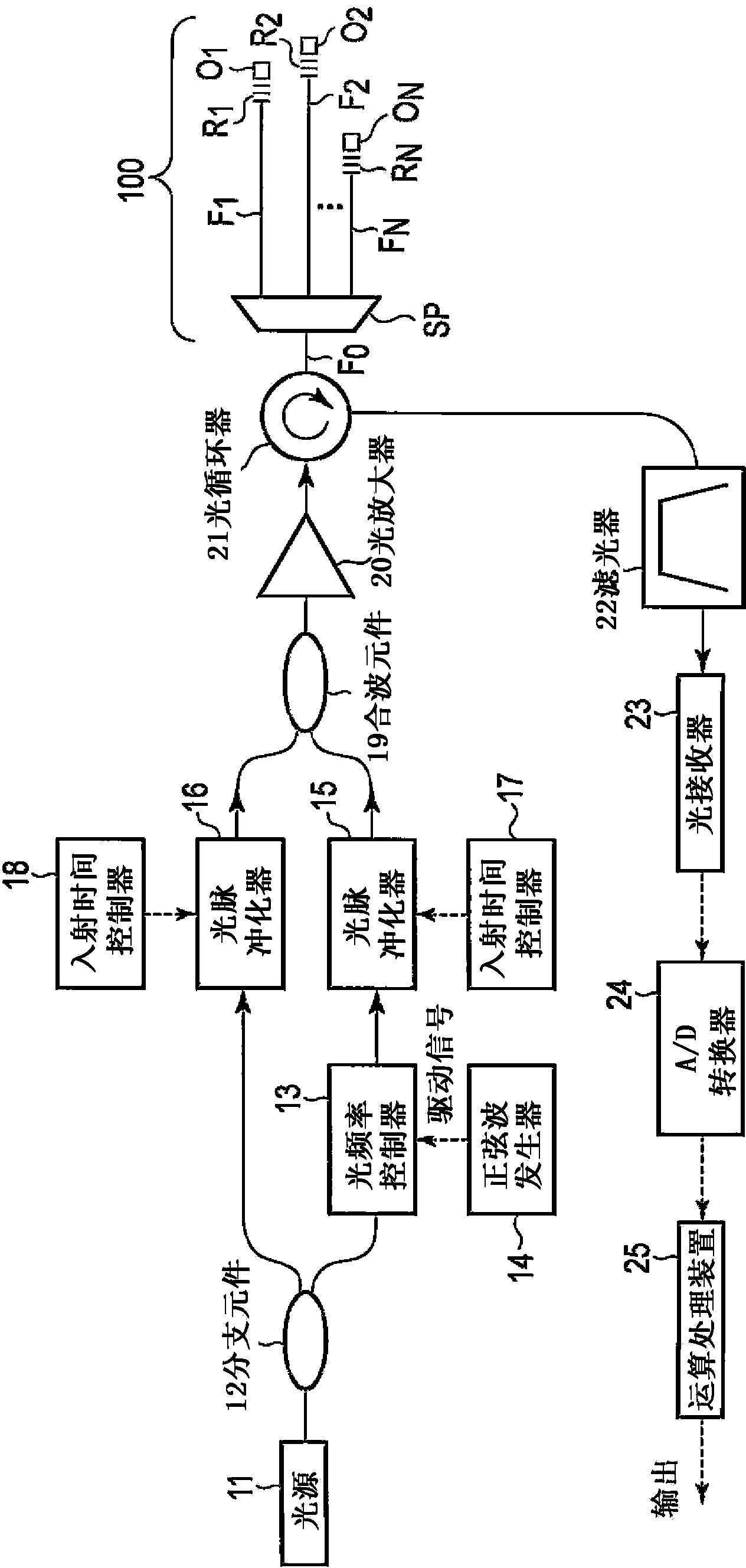
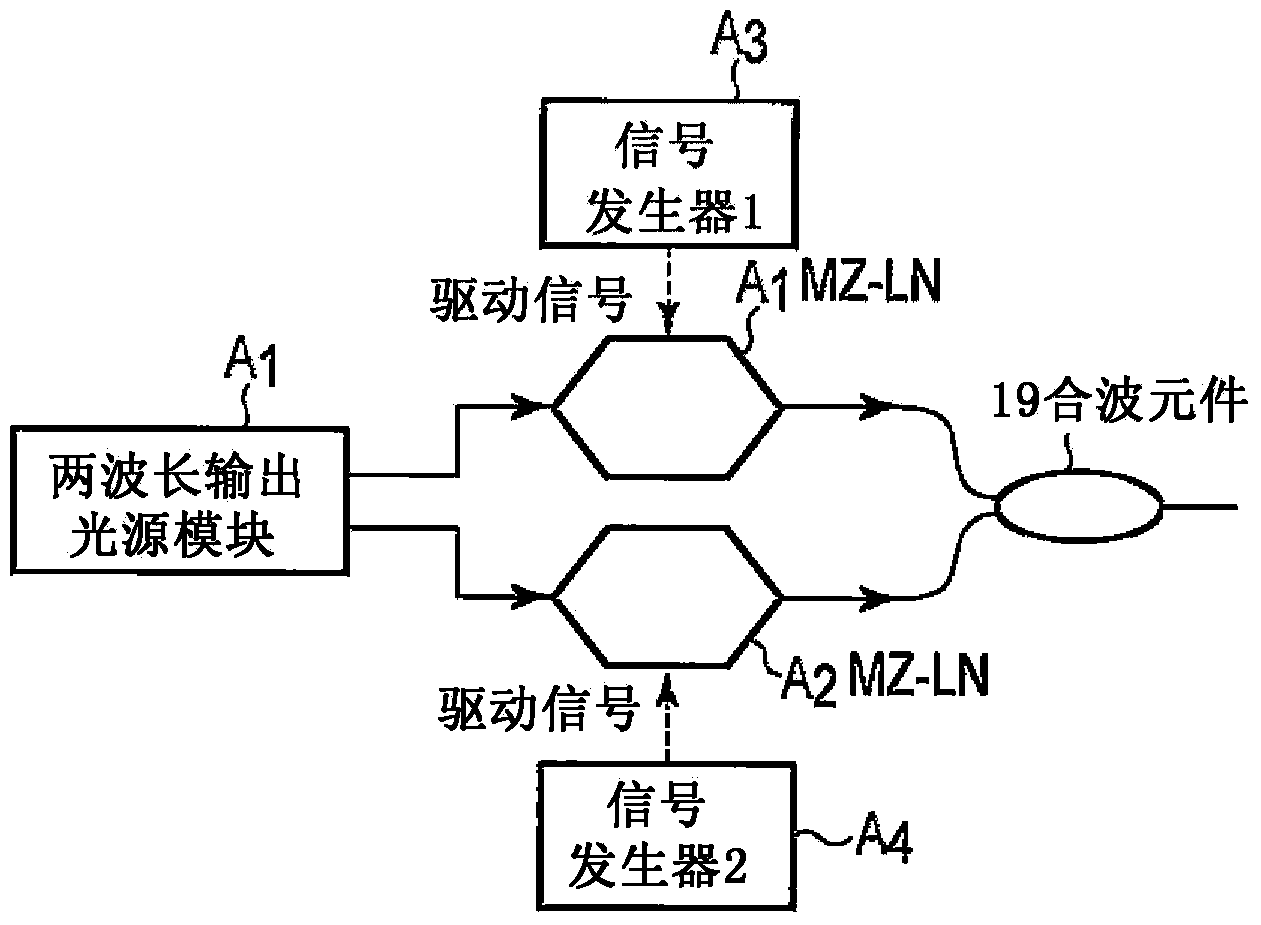
[0061] figure 1 It is a block diagram showing the configuration of an optical line characteristic analysis device according to an embodiment of the present invention. exist figure 1 Among them, 11 is to generate light frequency f 0 A continuous light source, the continuous light output from the light source 11 is branched into two systems by the branching element 12 . It is assumed that one of the branched continuous lights is the first test light (probe light), and the other is the second test light (pump light). The first test light is incident on the optical frequency controller 13, and the optical frequency f 0 offset by a certain frequency f B . Specifically, this optical frequency controller 13 can use an exte...


PUM


Abstract

In the present invention, with respect to an optical fiber path (100) to be tested that branches a backbone optical fiber (F0) into N systems of branched optical fibers (F1-FN) by means of an optical splitter (SP), an optical reflection filter (R1-RN) is disposed at each end of the branched optical fibers (F1-FN), a test optical pulse is generated from a first and second test optical pulse at a predetermined time difference from a first and second test light having differing wavelengths, by means of an optical circulator (21), the test optical pulse is caused to enter the backbone optical fiber (F0) of the optical fiber path (100) to be tested, and the return light exiting from the entrance end is taken out, the stimulated Brillouin backscattering light is extracted by an optical filter (22), and the scattering light is received by an optical receiver (23); and converted to an electrical signal, and the electrical signal is digitally processed while chanting the time difference of the first and second test optical pulses by means of a computational processing device (25), by which means it is determined which branched optical fibers (F1-FN) the stimulated Brillouin scattering light is from, and the characteristic distribution for each branched optical fiber is determined.

Description

technical field [0001] The present invention relates to an optical line characteristic analysis device and analysis method for individually measuring the characteristics of each optical branch line branched by an optical splitter, for example, in a PON (Passive Optical Network: Passive Optical Network) type optical line . Background technique [0002] In an optical communication system using an optical line such as an optical fiber, an optical pulse line monitoring device is used to detect breakage of the optical line or to identify a breakage position. This optical pulse line monitoring device utilizes the principle that as light propagates in the optical line, backscattered light having the same wavelength as the light is generated and propagated in the opposite direction. [0003] That is, when an optical pulse is incident on the optical line as test light, backscattered light continues to be generated until the optical pulse reaches the breaking point, and return light ...

Claims


Application Information

Patent Timeline
Patent Type & Authority Applications(China)
IPC IPC(8): G01M11/00
CPCG01M11/319G01M11/3109G01M11/3136
Inventor 高桥央伊藤文彦樊昕昱古敷谷优介
Owner NIPPON TELEGRAPH & TELEPHONE CORP
Learn More