Attachment device for a solar tile

A technology for fixing devices and solar energy, which is applied in the direction of solar thermal devices, fixed bases/supports of solar collectors, solar thermal energy, etc., and can solve problems such as inability to obtain tight sealing

Inactive Publication Date: 2014-02-12
SAINT-GOBAIN GLASS FRANCE
View PDF6 Cites 7 Cited by
  • Summary
  • Abstract
  • Description
  • Claims
  • Application Information

AI Technical Summary

Problems solved by technology

[0014] Thus, it has been revealed that while for relatively shallow slopes (14% for headwind and 6% for sidewind) the tightness remains correct for an overlap of 120 mm, this tightness cannot be obtained for an overlap of 50 mm. tightness

Method used


Image

  • Attachment device for a solar tile
  • Attachment device for a solar tile
  • Attachment device for a solar tile

Examples


Embodiment Construction

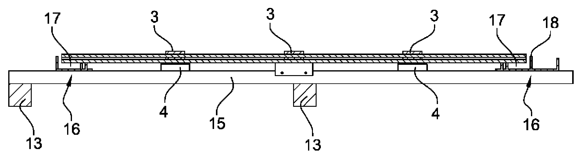
[0056] figure 1 A partial view of a solar roof 1 installed according to the invention on a structural frame 1A of a very simply illustrated dwelling is shown.

[0057] The roof has an outer face 10 facing the external environment and intended to receive light energy, and an opposite inner face 11 facing the structural frame 1A. It has a slope like most roofs.

[0058] The roof comprises a covering 2 formed by an association of flat solar tiles 20 .

[0059] Unlike photovoltaic modules, solar tiles do not have a frame.

[0060] The tiles comprise photovoltaic cells, possibly especially thin-film photovoltaic cells, the absorber layer of which is based on amorphous silicon or microcrystalline silicon, on chalcopyrite-type compounds, especially of the CIS or CIGS type, or on cadmium telluride. As a variant, photovoltaic cells may be constructed from monocrystalline or polycrystalline silicon wafers or organic photovoltaic cells forming P / N junctions. For each solar tile, the ...


PUM


Abstract

The present invention relates to an attachment device for a solar tile having a thickness of 4 mm, including for one tile at least three tile attachment hooks (3) combined with corresponding shims (4) for positioning the hooks and supporting the tiles. In addition, the hooks (3) are reinforced by adapted thickness and width dimensions and/or include a reinforcement means.

Description

technical field [0001] The invention relates to a fixing device for photovoltaic solar tiles. Background technique [0002] A photovoltaic solar tile is considered a flat photovoltaic element that jointly provides the functions of a photovoltaic module and a covering for a building roof in the manner of a standard tile or stone flake or other similar covering element. As is known, roof coverage is ensured by partial overlapping of the elements. [0003] Solar tiles are made of photovoltaic cells, possibly thin-film photovoltaic cells, for their absorber layers based on amorphous silicon or microcrystalline silicon, on chalcopyrite compounds, especially of the CIS or CIGS type, or on cadmium telluride. As a variant, photovoltaic cells may be constructed from monocrystalline or polycrystalline silicon wafers or organic photovoltaic cells forming P / N junctions. Regardless of its type, photovoltaic cells are usually laminated between two substrates that form the front and back...

Claims


Application Information

Patent Timeline
Patent Type & Authority Applications(China)
IPC IPC(8): H02S20/25F24J2/52E04D13/18E04D1/34
CPCY02B10/20E04D2001/3414F24J2002/0061E04D2001/3458F24J2/5247E04D1/34E04D2001/3473H01L31/0482F24J2/5205Y02E10/50Y02B10/12Y02E10/47F24S25/33F24S25/613F24S2020/13F24S2025/014H02S20/23Y02B10/10
Inventor D.茹斯S.埃尔卡斯米J-P.杜什
Owner SAINT-GOBAIN GLASS FRANCE
Why Eureka
Try Eureka