Eureka AIR delivers breakthrough ideas for toughest innovation challenges, trusted by R&D personnel around the world.

Ultra-precise three-axis association micro-milling device with micro-tool monitoring capacity

A three-axis linkage, ultra-precise technology, applied to fine working devices, manufacturing tools, stone processing equipment, etc., can solve the problem of difficult real-time observation and monitoring of processed surface quality, reduce the laser damage threshold of KDP crystals, shorten the service life of crystals, etc. problems, to achieve the effect of clear and reasonable cable layout, compact structure, and reduced structural size

Active Publication Date: 2014-02-19
HARBIN INST OF TECH
View PDF5 Cites 4 Cited by
  • Summary
  • Abstract
  • Description
  • Claims
  • Application Information

AI Technical Summary

Problems solved by technology

However, at this scale, traditional milling parameters and processing techniques are no longer suitable for micro-milling. For example, because the diameter of the micro-milling cutter is small, in order to achieve a certain line cutting speed, it is often necessary At the same time, people can hardly see the blade during the rotation with the naked eye, so it is difficult to perform the knife setting operation and real-time observation and monitoring of the processed surface quality with the naked eye. Microscope-assisted tool setting and real-time monitoring technology are used in micro It is very important in milling
In particular, in nuclear fusion ignition devices, if micro-defects are generated on the surface of the large-diameter KDP crystal element, it will grow rapidly during the subsequent high-energy laser targeting process, which greatly reduces the laser damage threshold of the KDP crystal and shortens the use of the crystal. life

Method used


Image

  • Ultra-precise three-axis association micro-milling device with micro-tool monitoring capacity
  • Ultra-precise three-axis association micro-milling device with micro-tool monitoring capacity
  • Ultra-precise three-axis association micro-milling device with micro-tool monitoring capacity

Examples


specific Embodiment approach 1

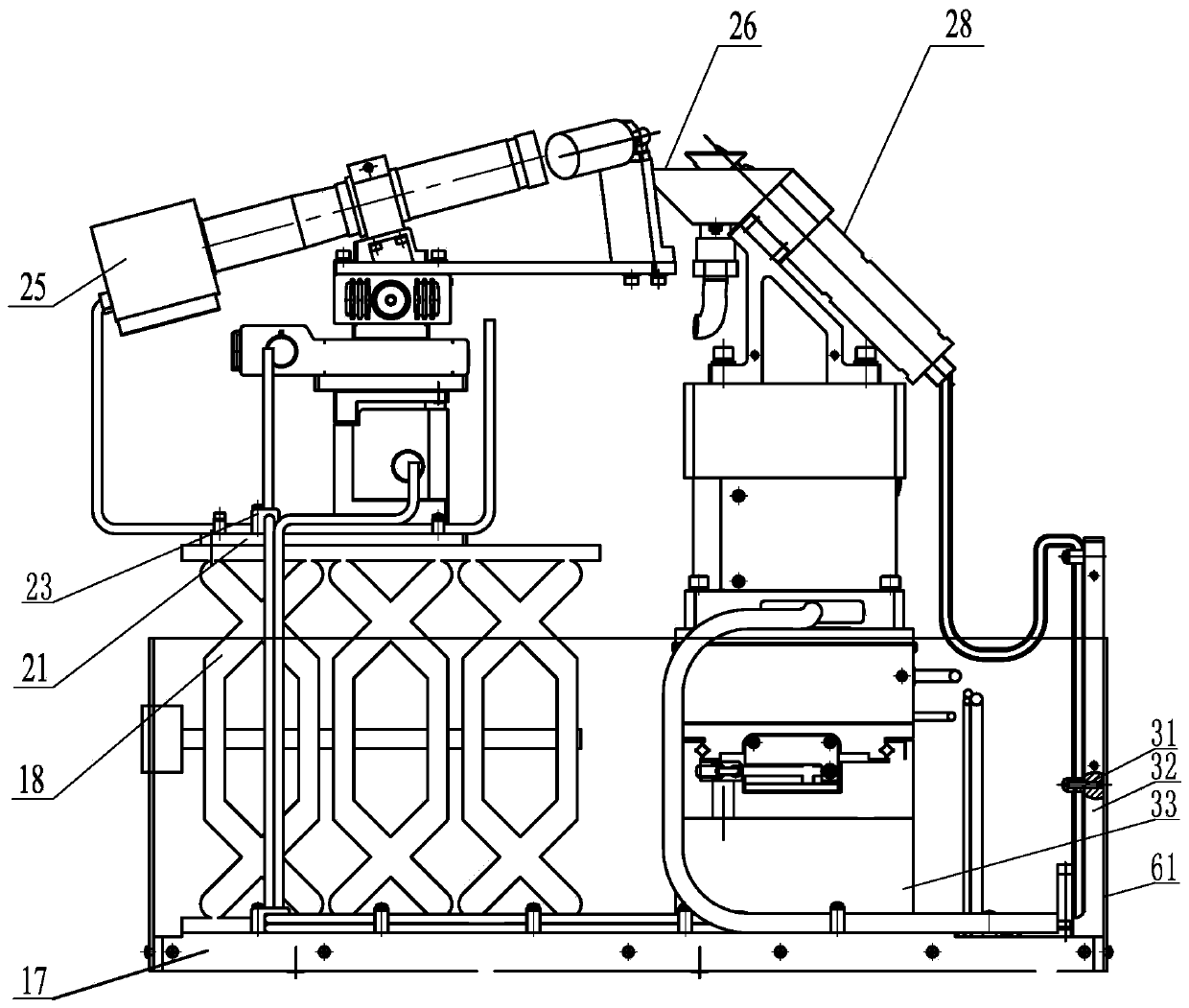
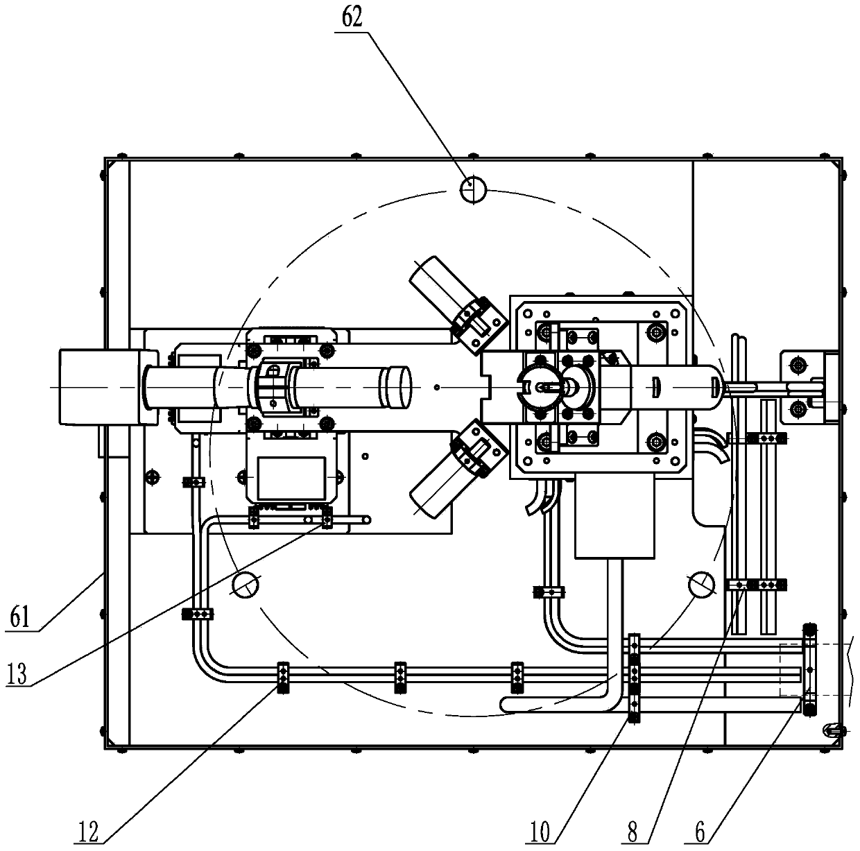
[0017] Specific implementation mode one: combine Figure 1 to Figure 14 Explain, an ultra-precision three-axis linkage micro-milling device with micro-tool monitoring capability in this embodiment, the ultra-precision three-axis linkage micro-milling device with micro-tool monitoring capability includes a bottom mounting plate 17, a manual lifting adjustment platform 18 , Microscope connection plate 21, tool microscope moving platform 25, chip collection assembly 26, tool three-axis linkage platform 28, tool moving part wiring board 32 and tool moving part pad 33;

[0018] The tool moving part wiring board 32, the tool moving part cushion block 33 and the manual lifting adjustment platform 18 are all fixed on the upper end surface of the bottom mounting plate 17, and the bottom mounting plate 17 is processed with three connecting holes 62 along its thickness direction, and the three connecting holes 62 are evenly distributed on the same circumference (for installing the device...

specific Embodiment approach 2

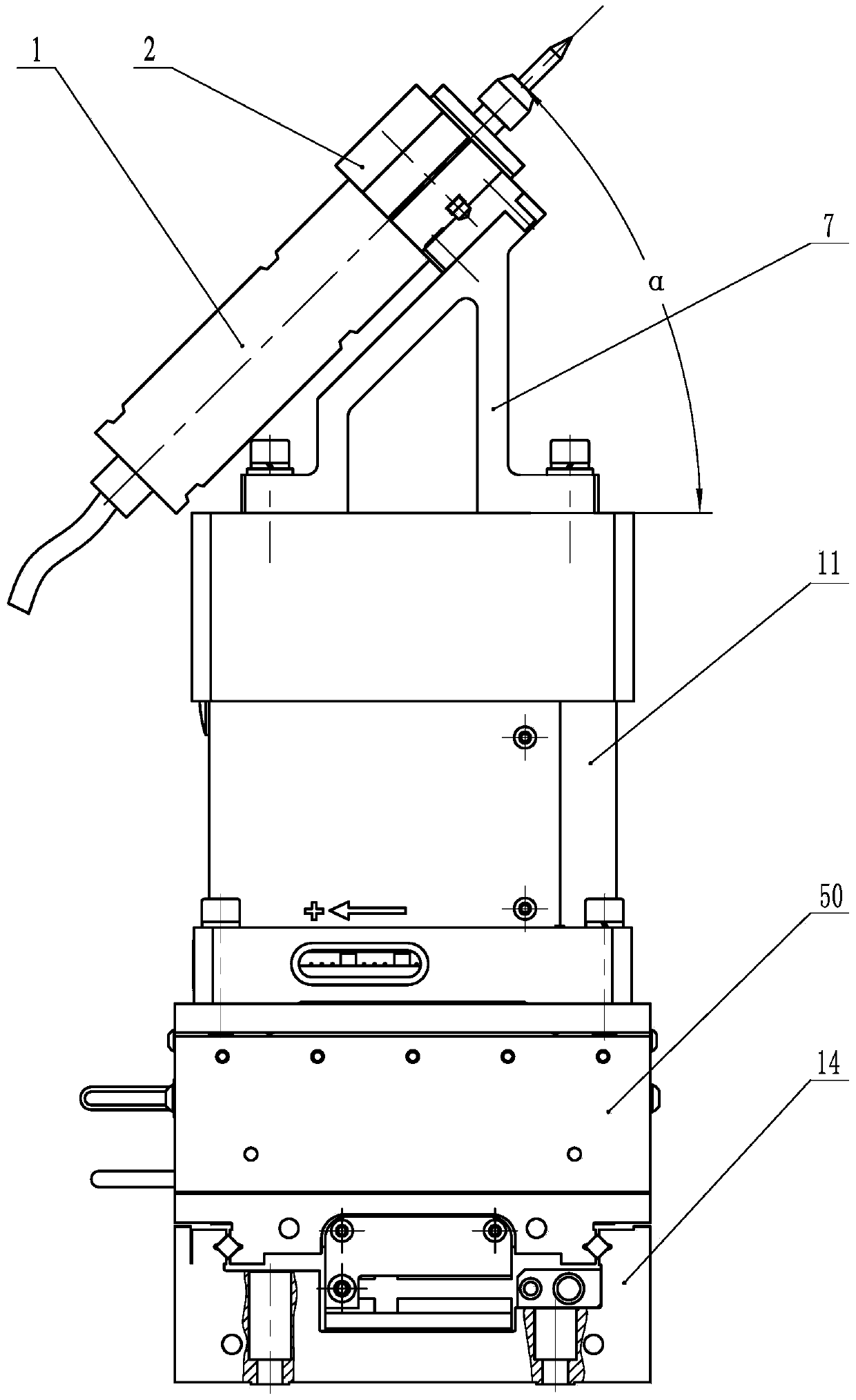
[0020] Specific implementation mode two: combination figure 1 and image 3 Note that the tool three-axis linkage platform 28 in this embodiment includes an electric spindle 1, an electric spindle fixture 2, a Z-axis connector 7, a tool movement Z-axis unit 11, a tool movement Y-axis unit 50, and a tool movement X-axis unit 14; The Z-axis connector 7, the tool movement Z-axis unit 11, the tool movement Y-axis unit 50, and the tool movement X-axis unit 14 are sequentially connected from top to bottom, and the electric spindle fixture 2 is located on the Z-axis connector 7 and the two are connected. , the electric spindle 1 is arranged in the electric spindle fixture 2, and the electric spindle 1 is clamped and fixed by the electric spindle fixture 2.

[0021] The tool three-axis linkage platform 28 realizes the high-speed rotation of the micro-milling tool and the high-precision three-axis linkage of the micro-milling tool through the high-speed rotation of the electric spindle...

specific Embodiment approach 3

[0024] Specific implementation mode three: combination figure 1 , Figure 7 and Figure 8 Note that the tool microscope moving platform 25 in this embodiment includes a light source connecting plate 51, a tool microscope Z-axis unit 54, a tool microscope rail connector 55, a tool microscope XY axis unit 56, a fixture connector 16, a monitoring microscope 63, and a tool microscope Fixture 19 and two light source assemblies, each light source assembly includes light source support 5, light source fixture 52 and CCS point light source 53; fixture connector 16, light source connection plate 51, tool microscope XY axis unit 56, tool microscope rail connector 55 and the tool microscope Z-axis unit 54 are sequentially connected from top to bottom, the tool microscope fixture 19 is fixed on the fixture connector 16, and the monitoring microscope 63 is installed in the tool microscope fixture 19 and fixed by the tool microscope fixture 19. The two light source supports 5 are connecte...


PUM


Abstract

The invention provides an ultra-precise three-axis association micro-milling device with micro-tool monitoring capacity, relates to an ultra-precise three-axis association micro-milling device, and aims to solve the problem that in the prior art, no equipment for repairing micro-defects on the surfaces of large-caliber KDP crystal elements exists. A tool moving part wiring board, a tool moving part cushion block and a hand-operated lifting adjustment platform are all fixed to the upper end face of a bottom installation flat board, a tool three-axis association platform is fixed to the tool moving part cushion block, a chip collection assembly is connected with the tool three-axis association platform, a tool microscope moving platform, the hand-operated lifting adjustment platform and a microscope connecting board are sequentially connected from top to bottom, and the microscope connecting plate is connected with the upper end face of the bottom installation flat board. The ultra-precise three-axis association micro-milling device is used for repairing the micro-defects on the surfaces of the large-caliber KDP crystal elements in an ultra-precise mode.

Description

technical field [0001] The invention relates to an ultra-precision three-axis linkage micro-milling device. Background technique [0002] At present, micro-milling is an important advanced manufacturing technology, which plays an important role in the fields of electronics, biology, and national defense. Usually the object of micro-milling research is that the processing feature size is on the order of microns to sub-millimeters, and the diameter of the milling cutter is generally less than 0.5mm. However, at this scale, traditional milling parameters and processing techniques are no longer suitable for micro-milling. For example, because the diameter of the micro-milling cutter is small, in order to achieve a certain line cutting speed, it is often necessary At the same time, people can hardly see the blade during the rotation with the naked eye, so it is difficult to perform the knife setting operation and real-time observation and monitoring of the processed surface qual...

Claims


Application Information

Patent Timeline
Patent Type & Authority Applications(China)
IPC IPC(8): B28D5/00
Inventor 陈明君肖勇郭占玥张文明李旦梁迎春
Owner HARBIN INST OF TECH
Why Eureka
Eureka Blog
Learn More