A vacuum coating machine
A technology of vacuum coating machine and vacuum cover, which is applied in the field of machinery, can solve the problems such as the decrease of the uniformity of the film on the surface of the plated workpiece, and achieve the effect of improving the heating situation, improving the processing efficiency, and good economic benefits
- Summary
- Abstract
- Description
- Claims
- Application Information
AI Technical Summary
Problems solved by technology
Method used
Image
Examples
Embodiment 1
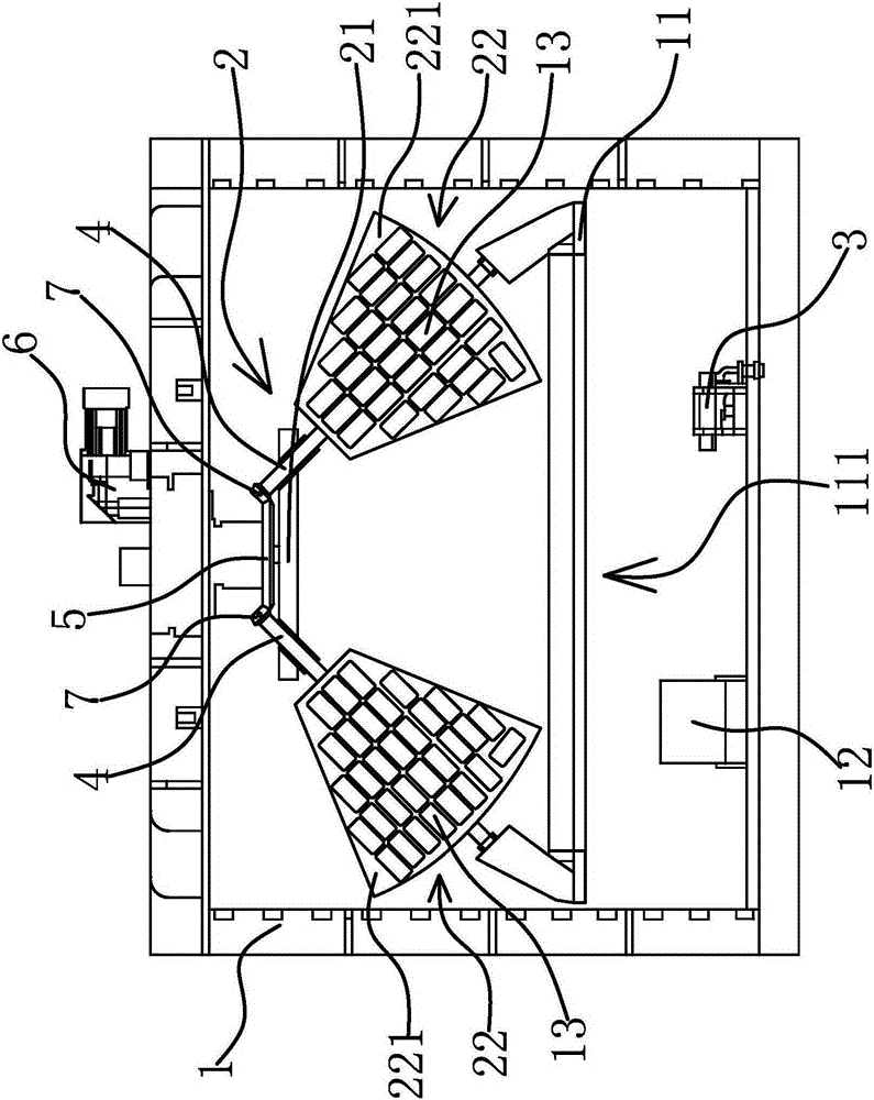
[0031] The vacuum coating machine includes a vacuum cover 1, a vacuum system, an umbrella stand 2, an evaporation source 3 and a driving mechanism.
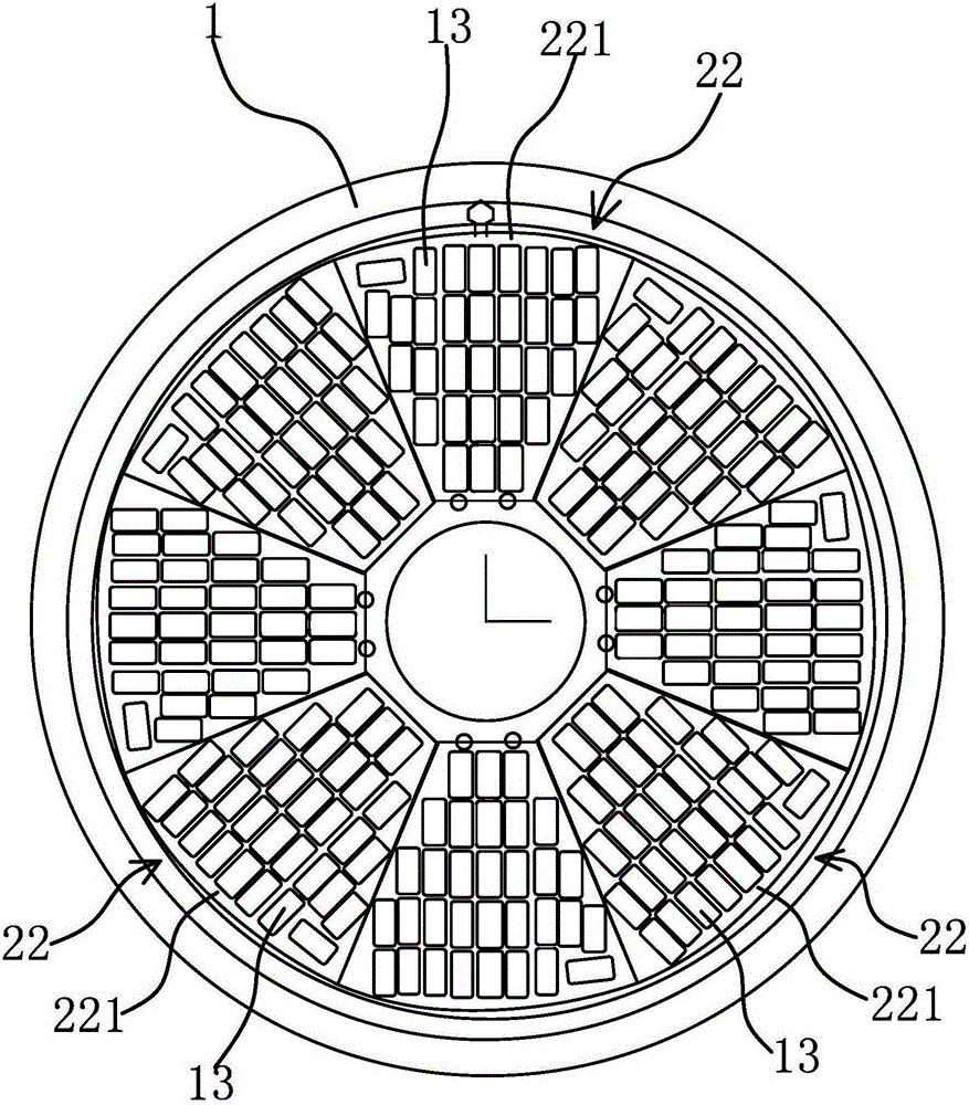
[0032] Specifically, as figure 1 As shown, the umbrella stand 2 includes a turntable 21 and a workpiece holder 22, the turntable 21 is connected with the vacuum cover 1 through a transmission shaft, and the transmission shaft can drive the rotating shaft to rotate in a circumferential direction. Such asfigure 1 and figure 2 As shown, the workpiece holder 22 is distributed in an umbrella shape along the circumferential direction of the turntable 21 , and the inclination angle of the workpiece holder 22 relative to the turntable 21 is less than 90°. A rotating shaft 4 is respectively fixed on the upper end of the workpiece holder 22, and the rotating disk 21 has mounting holes for the rotating shaft 4 to pass through, and the rotating shaft 4 is respectively packed into the corresponding mounting holes.
[0033] The driving mech...
Embodiment 2
[0039] The technical solution in this embodiment is basically the same as the technical solution in Embodiment 1, the difference is that, as Figure 4 As shown, in the present embodiment, the drive mechanism includes a friction track 8 and a drive motor 6, the friction track 8 is circumferentially distributed on the inner wall of the vacuum cover 1, the drive motor 6 is connected to the turntable 21 through a transmission pair, and the other end of the workpiece holder 22 is provided with a Rotating shaft one 4 center line is positioned at the rotating shaft two 9 on the same straight line, and the end of rotating shaft two 9 is fixedly connected with friction wheel 10, and friction wheel 10 can roll in friction track 8 so that workpiece holder 22 revolves around rotating shaft one 4 and rotating shaft two 9 centers The line turns. During the rotation of the workpiece holder 22 with the turntable 21, the second shaft 9 moves circumferentially along the friction track 8, and th...
Embodiment 3
[0041] The technical solution in this embodiment is basically the same as the technical solution in Embodiment 1. The difference is that in this embodiment, the drive mechanism includes a rotation motor and a revolution motor, and the revolution motor is connected to the turntable 21 through a transmission pair, and the rotation motors are respectively Link to each other with rotating shaft one 4 through transmission pair. The autorotation motor and the revolution motor respectively drive the autorotation and revolution of the workpiece rack 22, and the precise control of the autorotation and revolution of the workpiece rack 22 can be realized through the automatic control equipment.
PUM
 Abstract
Description
Claims
Application Information
 - R&D
- Intellectual Property
- Life Sciences
- Materials
- Tech Scout
- Unparalleled Data Quality
- Higher Quality Content
- 60% Fewer Hallucinations
Browse by: Latest US Patents, China's latest patents, Technical Efficacy Thesaurus, Application Domain, Technology Topic, Popular Technical Reports.
© 2025 PatSnap. All rights reserved.Legal|Privacy policy|Modern Slavery Act Transparency Statement|Sitemap|About US| Contact US: help@patsnap.com


