
Sanitary type side-blowing air distribution plate

An air distribution board and hygienic technology, applied in the field of fluidized bed, can solve the problems of increased processing difficulty, increased cost, high temperature denaturation, etc., and achieve the effect of easy control of size and processing, reduced processing difficulty and cost, and guaranteed strength.

Inactive Publication Date: 2014-02-19
陈林书
View PDF6 Cites 0 Cited by
  • Summary
  • Abstract
  • Description
  • Claims
  • Application Information

AI Technical Summary

Problems solved by technology

[0004] 1) As can be seen from the attached drawings, normally a plurality of beadings constitute the plane of the air distribution plate, because the contact between the beading and the substrate cannot be processed into absolutely seamless contact, so a dead angle or gap is formed between the beading and the substrate, and there is a problem Easy to clean, if the particle size of the material in the bed is smaller than this gap, the material will be stuck in this gap, which will easily lead to high temperature denaturation, which is unqualified for a hygienic fluidized bed
[0005] 2) It can also be seen from the drawings that because of the existence of the base plate, the bead cannot be designed to be vertically strengthened, and the strength of the bead itself is insufficient in the downward and upward directions, so the base plate is installed
[0006] 3) Because the base plate is set, a large number of strip holes and bolt holes will be processed on the base plate, which will lead to an increase in processing difficulty and cost

Method used


Image

  • Sanitary type side-blowing air distribution plate
  • Sanitary type side-blowing air distribution plate
  • Sanitary type side-blowing air distribution plate

Examples


Embodiment 2

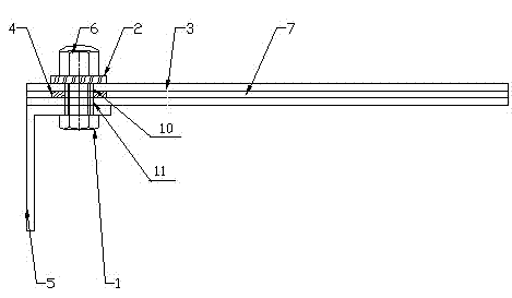
[0026] Example two such as Figure 4 As shown, the lower bolt hole ends of the various shaped slats 3 are bent downward to form a vertical reinforcement 8, and the ratio of the height of the vertical reinforcement 8 to the width of the special-shaped slat 3 is between 0.1:1 and 10:1. between. Through the design of the vertical reinforcement 8 of the special-shaped slat itself, the strength of each special-shaped slat 3 is sufficient, and the strength can be guaranteed without the base plate 9, which reduces the processing difficulty and cost.

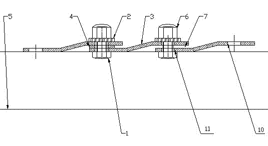
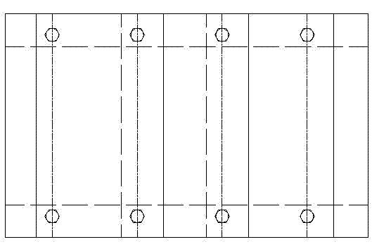
[0027] Embodiments are not limited to the above methods, such as Figure 5 As shown, a base plate 9 is set below each shaped slat 3, and the base plate 9 is provided with air inlet strip holes, bolt holes, and reinforced slats.

[0028] In the present invention, the various shaped slats 3 constitute air distribution channels without dead angles, which are very suitable for hygienic fluidized beds. The present invention can be applied ...


PUM


Abstract

The invention belongs to the technical field of fluidized beds, relates to an air distribution plate, in particular to a sanitary type side-blowing air distribution plate which can be applied to various fluidized bed granulating machines and drying(cooling) machines like multi-chamber fluidized beds granulating machines and drying(cooling) machine, internal heating fluidized bed granulating machines and drying(cooling) machines, and spray granulation fluidized bed granulating machines and drying(cooling) machines. The sanitary type side-blowing air distribution plate is mainly characterized in that the air distribution plate is composed of a plurality of specially-shaped slats, wherein end tails of the specially-shaped slats are sequentially connected in an overlapped mode, and the specially-shaped slats form an air distribution channel; bolt holes are formed in two end portions of each specially-shaped slat, two overlapped specially-shaped slats are fixed through bolts and nuts, and a gasket is arranged between every two overlapped specially-shaped slats. Compared with an air distribution plate mentioned in comparison files, the sanitary type side-blowing air distribution plate has the outstanding advantages that the dead-zone-free air distribution channel is formed among the air distribution slats, and therefore the sanitary type side-blowing air distribution plate is extremely suitable for sanitary type fluidized beds; through the vertical reinforcement design of the specially-shaped slats, the strength of the specially-shaped slats themselves can be sufficient, the strength can be guaranteed without a base plate, and machining difficulty and cost are reduced.

Description

technical field [0001] The present invention relates to an air distribution plate, in particular to a hygienic side blowing air distribution plate, which can be applied to various fluidized bed granulation such as multi-chamber fluidized bed, internal heating fluidized bed, spray granulation fluidized bed, etc. A drying (cooling) machine belongs to the technical field of fluidized beds. Background technique [0002] After searching, the utility model patent 201020531599.9 discloses a composite directional side blowing air distribution panel. The main features of this patent are that the base plate is provided with bolt holes and air inlets, the lower part of the base plate is provided with ribs, and the upper part of the base plate is provided with There is a bead, the bead is arranged on the upper part of the air inlet, the opening of the bead is the air outlet, the direction of the opening is consistent with the direction of the discharge end of the fluidized bed, the bead...

Claims


Application Information

Patent Timeline
Patent Type & Authority Applications(China)
IPC IPC(8): F26B3/08
Inventor 陈林书
Owner 陈林书
Learn More