Digital array radar amplitude-phase monitoring and calibration method based on optical fiber delay system

A digital array radar and optical fiber delay technology, applied in radio wave measurement systems, instruments, etc., can solve the problems of phased array antenna inconsistency accumulation, influence of radar overall performance, difficult operation and realization, etc., and achieve high practical application value, Improved operability and the effect of meeting the test accuracy requirements

Inactive Publication Date: 2014-02-19
THE 724TH RES INST OF CHINA SHIPBUILDING IND
View PDF2 Cites 21 Cited by
  • Summary
  • Abstract
  • Description
  • Claims
  • Application Information

AI Technical Summary

Problems solved by technology

However, the life cycle of radar in practical applications is relatively long. In the long-term use process, the inconsistency between the channels of the phased array antenna will gradually accumulate, and the system error will continue to increase. When the error is large to a certain extent, the performance of the antenna will deteriorate. Significantly decreased, affecting the overall performance of the radar
Therefore, it is necessary to be able to monitor the status of each channel in real time, but if the method of assuming an auxiliary antenna is used for each calibration, it will increase the difficulty of calibration and it is not easy to operate and realize on the ship

Method used


Image

  • Digital array radar amplitude-phase monitoring and calibration method based on optical fiber delay system
  • Digital array radar amplitude-phase monitoring and calibration method based on optical fiber delay system
  • Digital array radar amplitude-phase monitoring and calibration method based on optical fiber delay system

Examples


Embodiment Construction

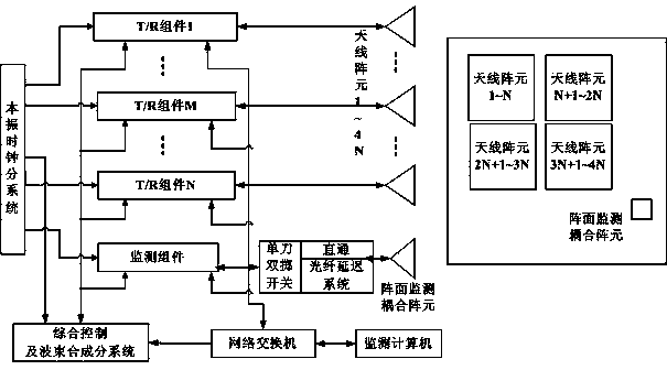
[0015] The present invention is based on the fact that after the antenna array is processed, its scattering matrix is ​​a constant value, and the mutual coupling characteristics of the antenna array are constant, and the mutual coupling of the radar array elements and the array monitoring coupling array elements is used to realize the radar array The up and down line amplitude and phase monitoring.

[0016] The specific steps for the implementation of uplink and downlink amplitude and phase monitoring. For the system framework, please refer to the attached figure 1 :

[0017] Uplink amplitude and phase monitoring steps:

[0018] When it is necessary to monitor a transmission channel of the antenna array, the integrated control and beam forming sub-system controls one of the transmitting units of the T / R component to work through the optical fiber, the single-pole double-throw switch is switched to the delay system, and the radio frequency signal passes through the antenna arr...


PUM


Abstract

The invention relates to a digital array radar amplitude-phase monitoring and calibration method based on an optical fiber delay system. The method mainly includes the steps that a radar array front array element and an array front monitoring coupled array element are utilized to collect amplitude-phase data of all uplink channels and all downlink channels of the radar array front array element in a mutual coupling mode, amplitude-phase monitoring of all the uplinks and the downlinks of a radar array front is finished, when amplitude-phase correction and calibration need to be conducted on the array front, the difference value between the amplitude-phase data and factory data is acquired through amplitude-phase monitoring, and then amplitude-phase calibration of the uplinks and the downlinks of the array front is finished after the difference value is corrected. According to the method, the optical fiber delay system is introduced to separate transmitting time from receiving time, within a transmitting monitoring operation time sequence, the monitored channels work in a deep blanking state, optical fiber amplitude-phase drifting self-calibration is finished, and accuracy of monitored data is guaranteed. The method has the advantages of being good in real-time performance, convenient and quick to operate, and good in cost performance. The presentation and engineering realization of the method have high practical application value in the field of digital array radar monitoring and calibration.

Description

technical field [0001] The invention belongs to a digital array radar monitoring and calibration method, which is applied to the amplitude and phase monitoring and calibration of the digital array radar array, and improves the accuracy and operability of the digital array radar amplitude and phase monitoring and calibration. Background technique [0002] At present, the monitoring and calibration methods of digital array radar mainly include: planar near-field calibration method, field direct measurement method, commutation measurement method, far-field monitoring method and internal monitoring method. The planar near-field calibration method is accurate in testing, but requires a heavy and precise mechanical scanning frame system, and the efficiency is very low; the field direct measurement method and the far-field monitoring method have a small amount of equipment, but they need to assume auxiliary antennas in the field and far fields; The monitoring method is mainly suita...

Claims


Application Information

Patent Timeline
Patent Type & Authority Applications(China)
IPC IPC(8): G01S7/40
CPCG01S7/4017
Inventor 田晓英张金良陈文锋
Owner THE 724TH RES INST OF CHINA SHIPBUILDING IND
Why Eureka
Try Eureka