
Finite element theory based direct current magnetic bias suppression method under condition of multiple direct-current falling points

A technology of DC bias suppression and DC falling point, which is applied in the direction of electrical digital data processing, special data processing applications, instruments, etc., can solve the problems that the computer cannot meet the requirements, the calculation model is large, and the calculation amount is increased, so as to achieve the solution capacity Effects of extended puzzles, simple numbering, and extended coverage

Inactive Publication Date: 2014-02-19
SHANGHAI MUNICIPAL ELECTRIC POWER CO +1
View PDF2 Cites 26 Cited by
  • Summary
  • Abstract
  • Description
  • Claims
  • Application Information

AI Technical Summary

Problems solved by technology

[0010] (1) The calculation model is huge, involving an area of ​​more than 7,000 square kilometers in Shanghai and the surrounding East China Sea, Hangzhou Bay, Yangtze River, etc.;
[0011] (2) The model is finely divided. In order to obtain a fine resistance network to improve the accuracy and applicability of the results, the model must be finely divided, which will further increase the amount of calculation;
[0012] (3) Due to the huge amount of computation, computers with conventional configurations cannot meet the requirements, and it is necessary to find a computing platform suitable for solving this problem

Method used


Image

  • Finite element theory based direct current magnetic bias suppression method under condition of multiple direct-current falling points
  • Finite element theory based direct current magnetic bias suppression method under condition of multiple direct-current falling points
  • Finite element theory based direct current magnetic bias suppression method under condition of multiple direct-current falling points

Examples


Embodiment Construction

[0063] The present invention will be further described below in conjunction with the accompanying drawings and embodiments.

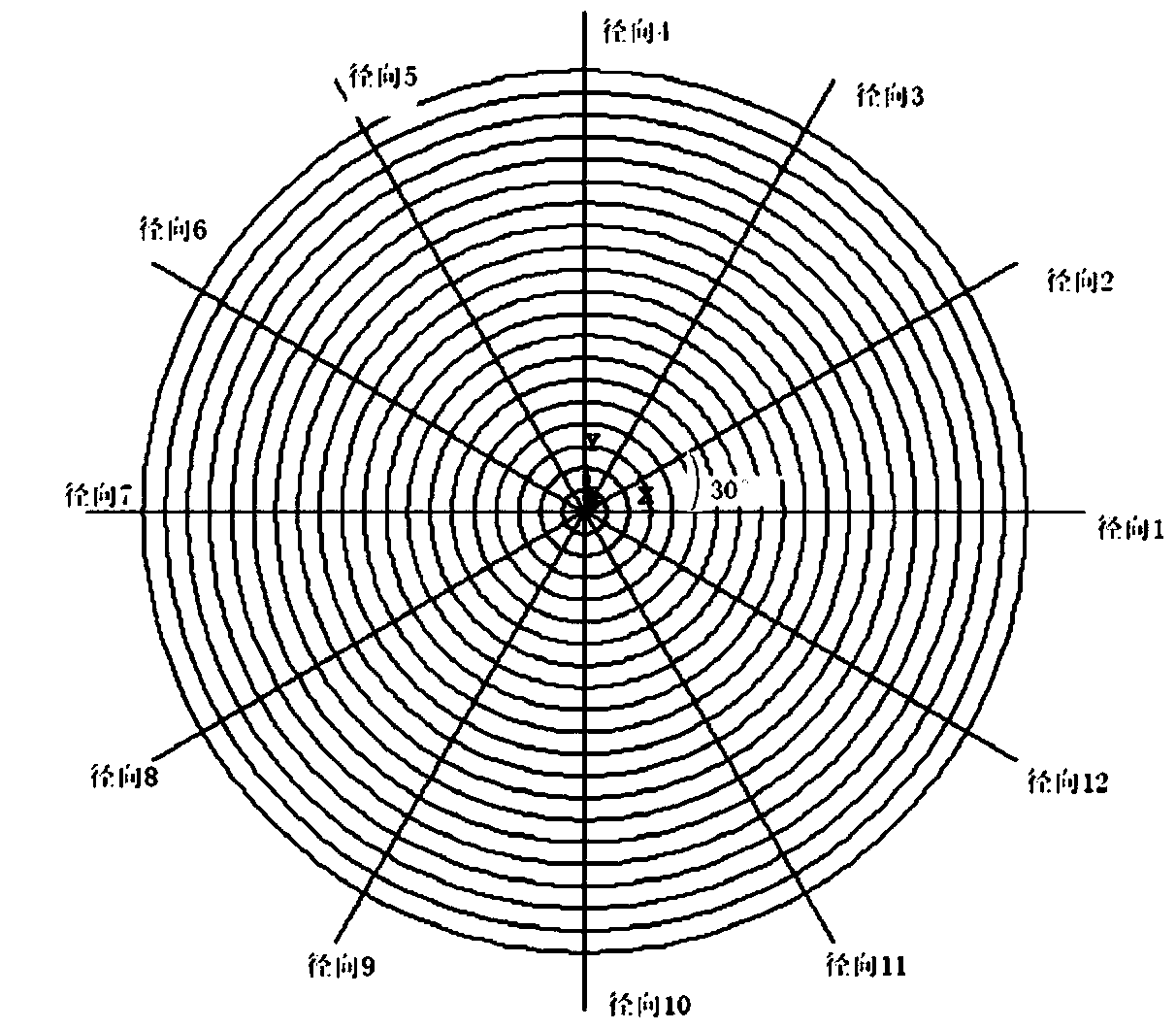
[0064] figure 1 Among them, the soil resistance network is not a simple series and parallel connection of several resistances, but a resistance network formed according to needs, and the number of resistance elements is generally not less than 10,000. According to the existing research results, the total radiation depth (radiation radius) of the soil resistance network is taken as 150km, the radiation angle is taken as 30°, and the resistance is extracted every 75m in the radial direction, including radial resistance and amplitude resistance, and the number of resistance elements reaches 48,000 indivual. From this, the top view schematic diagram of the soil resistance grid is obtained as follows: figure 1 shown.

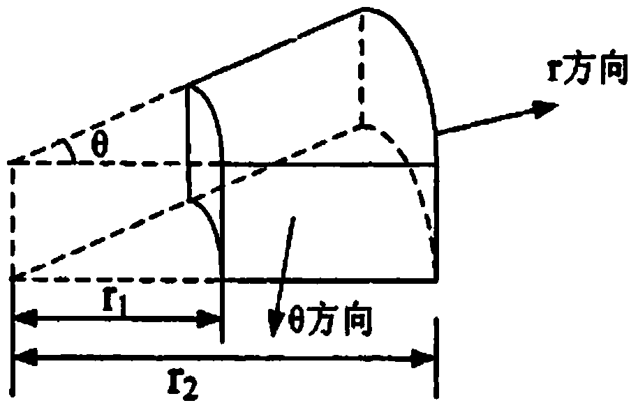
[0065] figure 2 for figure 1 A stereogram of a grid in , where each grid contains a radial resistance R r and amplitude resistance R ...


PUM


Abstract

The invention discloses a finite element theory based direct current magnetic bias suppression method under the condition of multiple direct-current falling points, and belongs to the field of direct current electric fields. According to the method, direct current electric fields are calculated with a finite element analysis method, the resistance in the direction parallel to the axis is obtained by calculating the radial resistance of the assigned specified soil grid, the distribution tendency of voltages and currents in the assigned direction is obtained, the current fields in different current falling points are determined, and the CDEGS software is adopted as a verification means; the current distribution curves corresponding to a plurality of directions are obtained to serve as the technical base for adopting the corresponding direct current magnetic bias suppression scheme in the following steps. Magnetic bias current calculating sub-models oriented to different power transmission systems can be respectively formed, the coverage range of the direct current magnetic bias research and the direct current magnetic bias suppression scheme is widened, and the simulating calculating efficiency is greatly improved. The method can be widely applied to the field of design, running and management of extra-high-voltage direct current power transmission lines.

Description

technical field [0001] The invention belongs to the field of direct current electric field, and in particular relates to a method for determining the current distribution and variation in an aboveground alternating current power network in a direct current electric field. Background technique [0002] With the continuous development of my country's power system, UHVDC transmission lines have gradually become an important corridor for trans-regional power transmission. [0003] DC power transmission projects usually use bipolar system wiring. During normal operation, DC current does not flow through the earth (or sea water). However, when the system is debugged, overhauled or malfunctioned, it is switched to a single-pole ground loop operation mode. The ground (or sea water) is equivalent to a wire of a DC transmission line, and its current field will change the ground potential. For an AC system with center point grounding, substations at different DC potentials form a DC c...

Claims


Application Information

Patent Timeline
IPC IPC(8): G06F17/50
CPCY02E60/76Y04S40/22Y02E60/00
Inventor 赵丹丹傅晨钊苏磊
Owner SHANGHAI MUNICIPAL ELECTRIC POWER CO
Learn More