

Direct-current side harmonic suppression system and method of 12-pulse rectification system on basis of interleaved Boost APFC circuit
A pulse wave rectification and harmonic suppression technology, applied in electrical components, output power conversion devices, etc., can solve the problems of difficulty in obtaining synchronization signals and suppressing harmonics, complex active circuit structure, etc., to improve the current tracking effect, Easy to obtain, the effect of reducing the harmonic content of the input current
- Summary
- Abstract
- Description
- Claims
- Application Information
AI Technical Summary
Problems solved by technology
Method used
Image

Examples
specific Embodiment approach 1
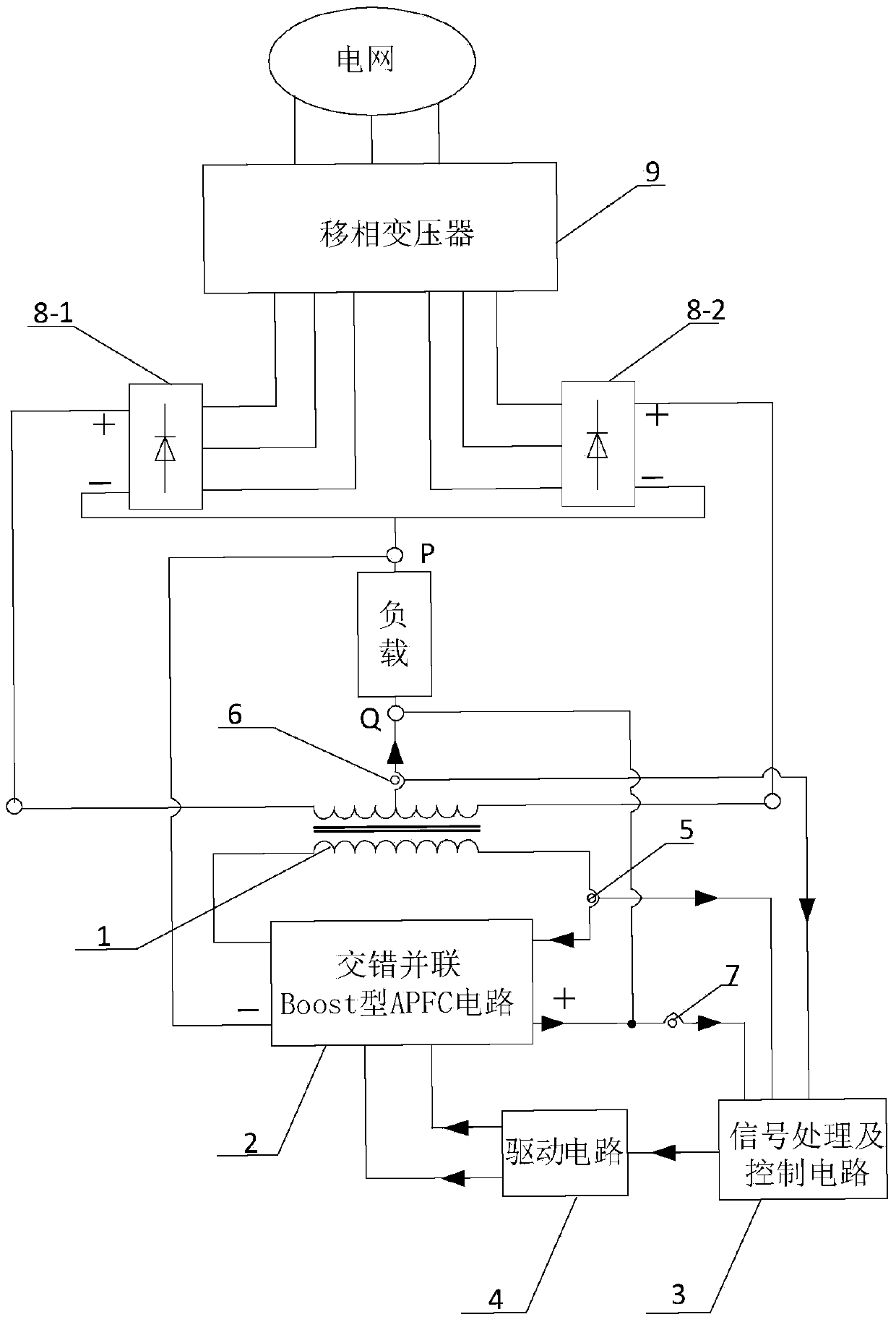
[0026] Specific implementation mode one: see figure 1 Describe this embodiment, the DC-side harmonic suppression system of the 12-pulse rectification system based on the staggered parallel Boost type APFC circuit described in this embodiment, it includes the first three-phase rectifier bridge 8-1, the second three-phase rectifier bridge 8-2 and phase-shifting transformer 9, which also includes balance reactor 1, interleaved parallel Boost type APFC circuit 2, signal processing and control circuit 3, drive circuit 4, No. 1 current sensor 5, No. 2 current sensor 6 and voltage sensor 7;
[0027] The three-phase input end of described phase-shifting transformer 9 is connected with grid, and the first three-phase output end of described phase-shifting transformer 9 is connected with the three-phase input end of first three-phase rectifier bridge 8-1, and described The second three-phase output end of the phase-shifting transformer 9 is connected with the three-phase input end of t...
specific Embodiment approach 2
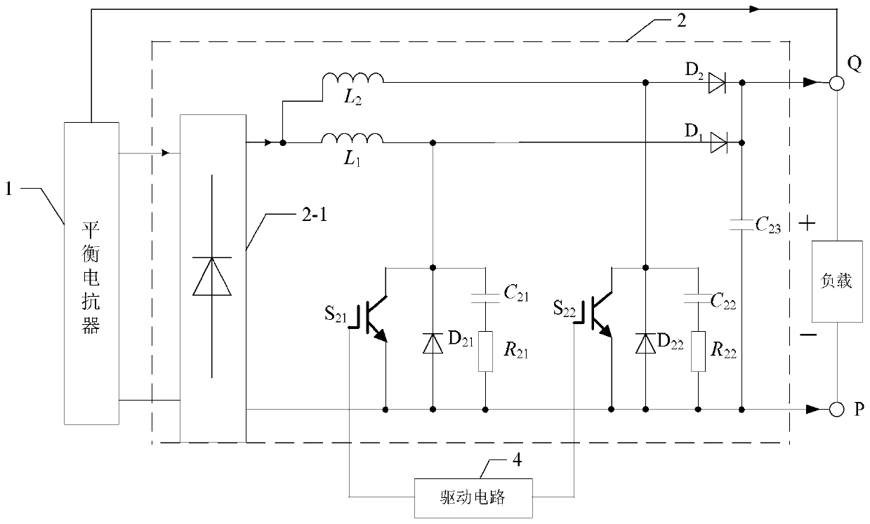
[0036] Specific implementation mode two: see figure 1 and 2 Describe this embodiment, the difference between this embodiment and the DC side harmonic suppression system of the 12-pulse rectification system based on the interleaved parallel Boost APFC circuit described in the first specific embodiment is that the interleaved parallel Boost APFC circuit 2 Including single-phase rectifier bridge 2-1, first inductor L 1 , the second inductance L 2 , the first diode D 1 , the second diode D 2 , the third diode D 21 , the fourth diode D 22 , the first capacitance C 21 , the second capacitance C 22 , the third capacitor C 23 , the first resistor R 21 , the second resistance R 22 , the first switch tube S 21 and the second switch tube S 22 ,
[0037] The AC signal input terminal of the single-phase rectifier bridge 2-1 is connected in parallel with the secondary winding of the balance reactor 1, and the positive pole output terminal of the DC side of the single-phase rect...
specific Embodiment approach 3
[0048] Specific implementation mode three: see figure 1 Describe this embodiment. The difference between this embodiment and the DC-side harmonic suppression system of the 12-pulse rectification system based on the interleaved parallel Boost APFC circuit described in the first embodiment is that the first switching tube S 21 is MOSFET or IGBT, the second switch tube S 22 for MOSFET or IGBT.
PUM
 Abstract
Description
Claims
Application Information