Method for temperature compensation in sensor, computation program for method for temperature compensation, computation processing device, and sensor

A temperature compensation and sensor technology, applied in the temperature compensation of the sensor, the calculation program of the temperature compensation, the calculation processing device, and the field of sensors, can solve the problems of difficult diaphragm thinning, increase pressure sensitivity, etc., and achieve high sensitivity effect

Inactive Publication Date: 2014-02-19
JAPAN SCI & TECH CORP
View PDF9 Cites 21 Cited by
  • Summary
  • Abstract
  • Description
  • Claims
  • Application Information

AI Technical Summary

Problems solved by technology

On the other hand, there is a disadvantage that since the inner cavity is sealed in a vacuum, for example, the diaphragm is greatly deformed under an external air pressure of 1 atmosphere, and it is difficult to make the diaphragm thinner as a pressure sensor used at about 1 atmosphere. increased pressure sensitivity

Method used


Image

  • Method for temperature compensation in sensor, computation program for method for temperature compensation, computation processing device, and sensor
  • Method for temperature compensation in sensor, computation program for method for temperature compensation, computation processing device, and sensor
  • Method for temperature compensation in sensor, computation program for method for temperature compensation, computation processing device, and sensor

Examples


no. 1 approach >

[0149] Below, refer to Figure 1-Figure 6 , the temperature compensation method of the sensor according to the first embodiment of the present invention will be described.

[0150] (Structure of Capacitive Sensor 100 )

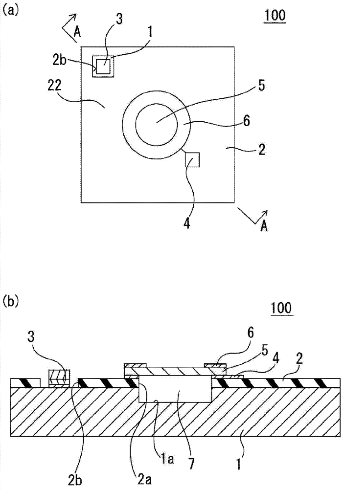
[0151] Such as figure 1 As shown in (a) and (b), the capacitance type sensor (sensor) 100 to which the calculation result of the temperature compensation method of the capacitance type sensor is applied includes a substrate 1 , an insulator layer 2 , a first electrode portion 3 , and a second electrode portion (conductive part) 4 , diaphragm part 5 , temperature compensation ring (temperature compensation member) 6 , and sealed space 7 .

[0152] The substrate 1 is made of a semiconductor such as silicon, and has a circular concave portion 1 a in a substantially central portion.

[0153] The insulator layer 2 is a layer made of an insulator such as silicon dioxide, and is formed on one surface of the substrate 1 . In addition, the insulator layer 2 has a cir...

no. 2 approach >

[0195] Next, use Figure 7-Figure 10 , the temperature compensation method of the sensor according to the second embodiment of the present invention will be described. In addition, since the positions 1-7 of the capacitance sensor 100 to which the calculation result of the temperature compensation method of the first embodiment is applied and the positions 21-27 of the capacitance sensor 200 to which the calculation result of the temperature compensation method of the present embodiment are applied (Some parts are not shown) are the same parts in order, so the description may be omitted.

[0196] (Structure of Capacitive Sensor 200 )

[0197] Such as Figure 7 As shown, the capacitive sensor (sensor) 200 includes the same substrate 21, insulator layer 22, first electrode part 23, second electrode part (conductive part) 24, diaphragm part 25, temperature The compensation ring (temperature compensation member) 26 , the closed space 27 , and a first barrier metal layer 28 are ...

no. 3 approach >

[0205] Next, use Figure 11-Figure 14 , the temperature compensation method of the sensor according to the third embodiment of the present invention will be described. In addition, since the positions 1-7 of the capacitance sensor 100 to which the calculation result of the temperature compensation method of the first embodiment is applied and the positions 31-37 of the capacitance sensor 300 to which the calculation result of the temperature compensation method of the present embodiment are applied (Some parts are not shown) are the same parts in order, so the description may be omitted.

[0206] (Structure of Capacitive Sensor 300 )

[0207] Such as Figure 11 As shown, the capacitive sensor (sensor) 300 has the same substrate 31 as the above-mentioned capacitive sensor 100, an insulator layer 32, a first electrode part 33, a second electrode part 34, a diaphragm part 35, a temperature compensation ring (temperature compensating member) 36 , a closed space 37 , and a seal ...


PUM


Abstract

[Problem] To provide a method for temperature compensation in a sensor, a computation program for the method for temperature compensation, a computation processing device for computationally processing the computation program, and a sensor, in which deformation in a diaphragm caused by a pressure change (thermal expansion of a gas sealed in a cavity) due to the temperature of the gas in the cavity is cancelled out, and deformation of the diaphragm is minimized within the target temperature range, thereby allowing an optimum temperature compensation to be performed. [Solution] This method for temperature compensation in a capacitance-type sensor comprises executing calculation steps which include including a calculation step (S17) of acquiring the amount of change ?C' in capacitance, whereby there is obtained a parameter ?C' through which it is possible to determine the degree of compensation for the deformation in the diaphragm section caused by a pressure change (thermal expansion of the gas sealed in a hermetically sealed space) due to the temperature of the gas in the hermetically sealed space.

Description

technical field [0001] The present invention relates to a temperature compensation method of a sensor, a calculation program of the temperature compensation method, a calculation processing device for calculating and processing the calculation program, and a sensor to be subjected to the temperature compensation. Background technique [0002] Conventionally, for semiconductor pressure sensors, it is generally composed of a tiny cavity and a thin diaphragm (diaphragm) covering its surface, and the resistance formed on the surface is measured by the deformation of the diaphragm deformed by external pressure. Change, or set another electrode at the corresponding position, and form a pressure gauge by measuring the capacitance change of the diaphragm and the counter electrode. [0003] In a pressure sensor with such a structure, in the case of a vacuum-sealed inner cavity, the diaphragm is deformed based on the pressure difference between the external air pressure and the vacuum...

Claims


Application Information

Patent Timeline
Patent Type & Authority Applications(China)
IPC IPC(8): G01L19/04G01L9/00
CPCG01L9/00G01L19/04B81B3/0081B81B2201/0264G01L9/0073G01L9/125
Inventor 郝秀春蒋永刚藤田孝之樋口行平前中一介高尾英邦
Owner JAPAN SCI & TECH CORP
Why Eureka
Try Eureka