Nitromethane synthesis reaction tower

A synthesis reaction, nitromethane technology, applied in the chemical method of liquid-liquid reaction, preparation of organic compounds, chemical instruments and methods, etc., can solve the problem of unsatisfactory nitromethane synthesis reaction, production process interruption, production work Inconvenience and other problems, to reduce the risk of safety and environmental protection, reduce waste, and fully respond

Active Publication Date: 2014-02-26
LINYI YUANBO CHEM IND
View PDF4 Cites 0 Cited by
  • Summary
  • Abstract
  • Description
  • Claims
  • Application Information

AI Technical Summary

Problems solved by technology

The existing reaction tower can only meet the simple gas-liquid contact reaction of general materials, and the synthesis process of nitromethane is a reaction between two liquid materials, and gas by-products are produced when the liquid materials react, and nitromethane The synthesis reaction of the compound is an unstable nitration reaction with high requirements on reaction conditions such as temperature and pressure. The raw materials sodium nitrite and dimethyl sulfate react violently and release heat quickly, and the requirements for the synthesis reaction tower are also very high. , so the general reaction tower cannot meet the needs of nitromethane synthesis reaction
[0003] The existing nitromethane synthesis process is generally carried out by using glass-lined reactors. In order to ensure full reaction, it takes a long time for the raw materials to fully react, which causes interruptions in the production process, and the reaction will still be incomplete. Inhomogeneous, slow reaction speed, low reaction efficiency, in addition, the synthesis process of nitromethane will generate a lot of heat, and the characteristics of the glass-lined reactor itself require that the temperature in the reactor should not be too high, so continuous external jacket cooling and cooling are required. Stirring and mixing to ensure the temperature in the kettle, high energy consumption, and inconvenience to production work

Method used


Image

  • Nitromethane synthesis reaction tower
  • Nitromethane synthesis reaction tower

Examples


Embodiment Construction

[0013] In order to make the technology, features, purposes and effects of the present invention easier to understand and understand, the technical solution of the present invention will be clearly and completely described below in conjunction with the accompanying drawings of the present invention, but the present invention is not limited thereto.

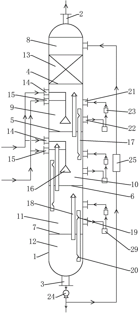
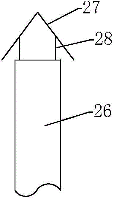
[0014] Such as Figure 1-Figure 2 As shown in , this embodiment includes a tower body 1, the top gas outlet 2 and the material outlet 3 are respectively provided at the top and bottom of the tower body 1, and the first tray 4 arranged in sequence from top to bottom in the tower body 1 , the second tray 5, the third tray 6 and the fourth tray 7 divide the interior of the tower body 1 from top to bottom into the first tower chamber 8, the second tower chamber 9, the third tower chamber 10, the fourth tower chamber The tower chamber 11 and the fifth tower chamber 12, the first tray 4 is a sieve tray, the upper surface of the first tra...


PUM


Abstract

The invention relates to the field of chemical engineering and especially discloses a nitromethane synthesis reaction tower. The nitromethane synthesis reaction tower comprises a tower body. The top and the bottom of the tower body are provided respectively with a top gas outlet and a material outlet. Through a first tower plate, a second tower plate, a third tower plate and a forth tower plate orderly arranged in the tower boy from top to bottom, the tower boy is orderly divided into a first tower chamber, a second tower chamber, a third tower chamber, a forth tower chamber and a fifth tower chamber from top to bottom. The side wall of each one of the second tower chamber and the third tower chamber is provided with a first material inlet and a second material inlet. An overflow cylinder for communicating the upper and lower tower chambers and a gas channel are arranged between each two adjacent tower chambers of the second tower chamber, the third tower chamber, the forth tower chamber and the fifth tower chamber. The nitromethane synthesis reaction tower has the advantages of simple processes, continuous production, full and uniform synthesis reaction, fast reaction rate, high production efficiency, energy saving and consumption reduction.

Description

(1) Technical field [0001] The invention relates to the field of chemical industry, in particular to a nitromethane synthesis reaction tower. (2) Background technology [0002] The reaction tower is a device commonly used in chemical production to react two or more materials at a certain pressure and temperature. It is often used in the countercurrent contact reaction of gas and liquid. In general, after the materials enter the tower, under the condition of steam or other external heating (or cooling), the materials will undergo chemical reactions due to the characteristics of the materials. Most of the common reaction towers in chemical production use liquid materials to enter from the top of the tower (tower side), gas materials to enter from the side of the bottom of the tower, and the final product is extracted from the bottom of the tower, and the heat exchanger installed inside the tower is used The heat required for the reaction is forced to circulate by the external...

Claims


Application Information

Patent Timeline
Patent Type & Authority Applications(China)
IPC IPC(8): B01J14/00C07C205/02C07C201/10
Inventor 陈功玉
Owner LINYI YUANBO CHEM IND
Why Eureka
Try Eureka