Metal plate feeding, discharging and cutting method and system

A metal plate and laser cutting head technology, which is applied in metal processing, metal processing equipment, welding/cutting auxiliary equipment, etc., can solve the problems of difficult to ensure joint cutting of multiple equipment, high equipment investment in floor space, etc. Achieve the effects of expanding the range of processing materials, low device investment cost, and small floor space

Active Publication Date: 2014-02-26
BAOSHAN IRON & STEEL CO LTD +1
View PDF8 Cites 34 Cited by
  • Summary
  • Abstract
  • Description
  • Claims
  • Application Information

AI Technical Summary

Problems solved by technology

However, there are still many technical difficulties in this method, for example, it is difficult to ensure that the slits of multiple equipments are connected at the same time when multiple cutting heads are operating at the same time; the influence of the deviation of the plate shape on the cutting shape, etc.
The huge configuration and floor area of ​​multiple sets of laser cutters and cutting units also form a high investment in equipment

Method used


Image

  • Metal plate feeding, discharging and cutting method and system
  • Metal plate feeding, discharging and cutting method and system
  • Metal plate feeding, discharging and cutting method and system

Examples


Embodiment Construction

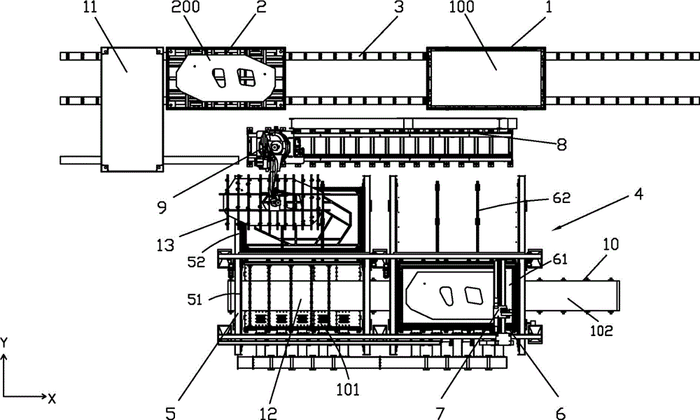
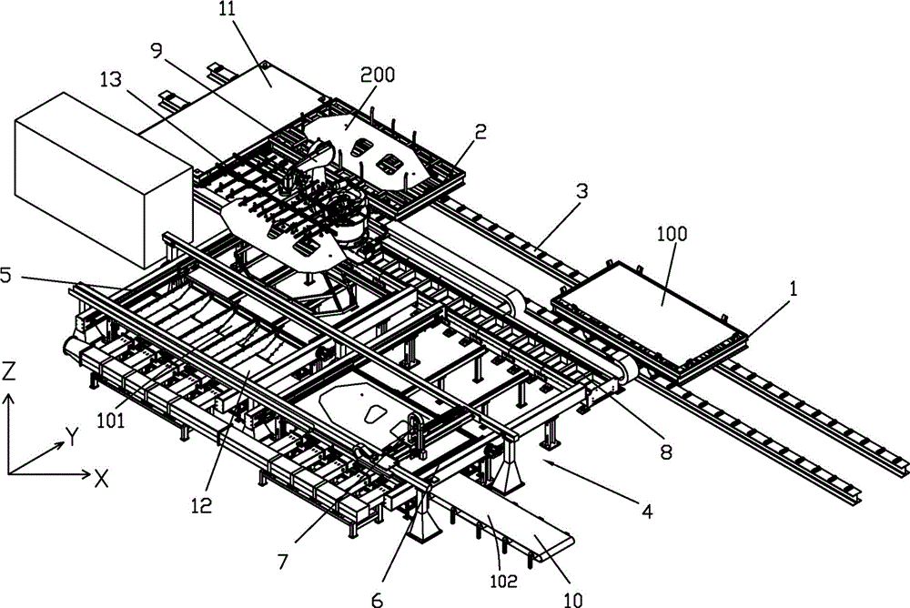
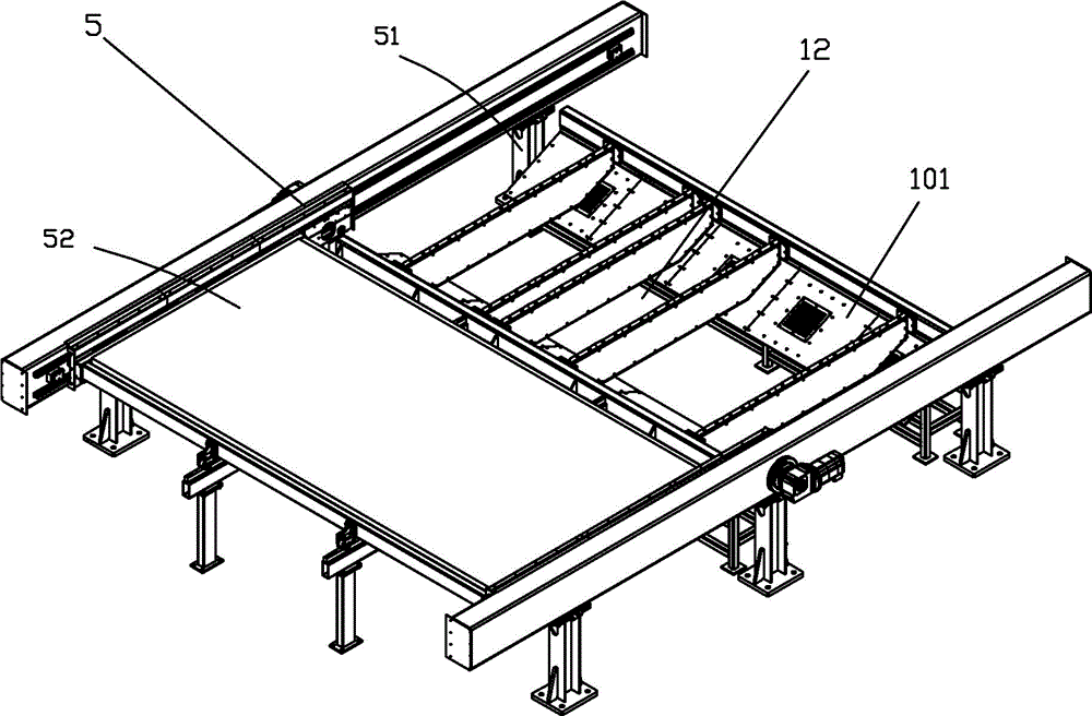
[0031] see Figure 1 to Figure 6 , the metal plate loading and unloading and cutting system of the present invention, it comprises: assembly trolley 1, sheet material trolley 2, are arranged on a guide rail 3 altogether; Cutting work unit 4, are arranged on described guide rail side, and it comprises two parallel Arranged first and second mobile fast tables 5, 6 and a laser cutting head 7; the two mobile fast tables 5, 6 are vertically arranged with the guide rail 3, and cutting positions 51, 61 and waiting positions 52 are arranged on it , 62; the laser cutting head 7 spans two cutting positions 51, 61 through its guide rail; the waiting material positions 52, 62 correspond to the group material trolley 1, the sheet material trolley 2 guide rail 3 sides; the handling and stacking robot 9, It is arranged between the cutting work unit 4 and the guide rails 3 of the assembly trolley and the piece trolley, and the external axis 8 of the robot is parallel to the guide rail 3 of th...


PUM


Abstract

A metal plate feeding, discharging and cutting method and system comprises a group material trolley, a sheet material trolley, a cutting working unit, a moving and stacking robot and a waste material conveying device. The group material trolley and the sheet material trolley are arranged on a guide track. The cutting working unit is arranged on one side of the guide track and comprises a first fast moving table and a second fast moving table which are arranged in parallel and further comprises a laser cutting head. The two fast moving tables are perpendicular to the guide track and provided with cutting positions and material waiting positions. The laser cutting head crosses two cutting positions through the guide track. The material waiting positions correspond to the group material trolley and the sheet material trolley and are arranged on one side of the guide track. The moving and stacking robot is arranged between the cutting working unit and the guide track of the group material trolley and the sheet material trolley. An external shaft of the robot is parallel to the trolley guide track and crosses the material waiting positions of the two fast moving tables of the cutting working unit. The waste material conveying device is arranged below the two cutting positions of the cutting working unit. By means of the method and system, use efficiency of materials can be effectively improved, production and machining range is further expanded, and the method and system is especially suitable for production of small-batch trolley models and trial production of new models.

Description

technical field [0001] The invention relates to metal processing, in particular, the invention relates to a method and a system for loading, unloading and cutting of metal plates in the technical field of automobile manufacturing. Background technique [0002] The existing auto sheet blanking adopts the mold blanking method, and the steel factory or the automobile factory usually has an automatic production line for uncoiling, shearing and stacking. Its equipment consists of: conveying unit, press unit and stacking unit. [0003] According to the above-mentioned mold blanking method, simple blank shapes (such as rectangle, trapezoid and arc) can be cut by pendulum cutting, and complex curve blanks can be blanked by mold. At this time, the blanking line needs to configure different blanking molds according to the size and shape of the blanks of the vehicle model, and produce different blanks by changing the molds. The metal plate blanking line in the automobile manufacturin...

Claims


Application Information

Patent Timeline
IPC IPC(8): B23K26/38B23K26/70B23K26/08
CPCB23K26/702B23K26/38B23K37/0211B23K2101/16B23K2101/006B23K37/0217B23K37/0408
Inventor 杨赛丹吴瑞珉金文海王玉明潘胜波项前阎启金成国乔俊良
Owner BAOSHAN IRON & STEEL CO LTD
Why Eureka
Try Eureka