

Automatic coal dredging device for raw coal conveying system in thermal power plant
A technology for thermal power plants and conveying systems, applied in the directions of transportation and packaging, packaging, containers, etc., can solve the problems of large operation and maintenance workload, unstable combustion of boilers, and high labor intensity, so as to ensure normal coal supply and safe operation. Reliable, economical results
- Summary
- Abstract
- Description
- Claims
- Application Information
AI Technical Summary
Problems solved by technology
Method used
Image

Examples
Embodiment Construction
[0020] Below in conjunction with accompanying drawing and specific embodiment the present invention is described in further detail:
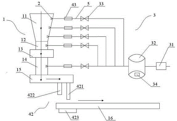
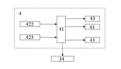
[0021] An automatic coal dredging device used in the raw coal conveying system of a thermal power plant, its structure diagram is as follows figure 1 shown. It includes an air supply system 3, a control system 4 and several air injection ports 2, wherein the air injection ports 2 are installed on the inner walls of each equipment of the raw coal conveying system 1, and the air injection ports 2 communicate with the air supply system 3 through the air pipe 5, and the air supply system 3. Change the working state under the control of the control system 4.
[0022] The raw coal conveying system described in this embodiment includes a raw coal hopper 11, a variable diameter pipe 12, a gate valve 13, a coal drop pipe 14, a coal feeder 15, a conveyor belt 16, and a gas injection port that are sequentially arranged in accordance with the raw coal conv...
PUM
 Abstract
Description
Claims
Application Information