
Test structure of micro-machining residual stress of deflection capacitive surface

A micromachining and residual stress technology, applied in the direction of measuring force, measuring device, instrument, etc., can solve the problems of film structure rupture and deformation, achieve the effect of large capacitance change, simple test structure, and improve measurement accuracy

Inactive Publication Date: 2014-02-26
SOUTHEAST UNIV
View PDF6 Cites 7 Cited by
  • Summary
  • Abstract
  • Description
  • Claims
  • Application Information

AI Technical Summary

Problems solved by technology

[0003] However, residual stress will inevitably be generated during surface micromachining, and excessive residual stress will cause cracking or deformation of the film structure

Method used


Image

  • Test structure of micro-machining residual stress of deflection capacitive surface
  • Test structure of micro-machining residual stress of deflection capacitive surface

Examples


Embodiment Construction

[0017] The present invention will be further explained below in conjunction with the accompanying drawings.

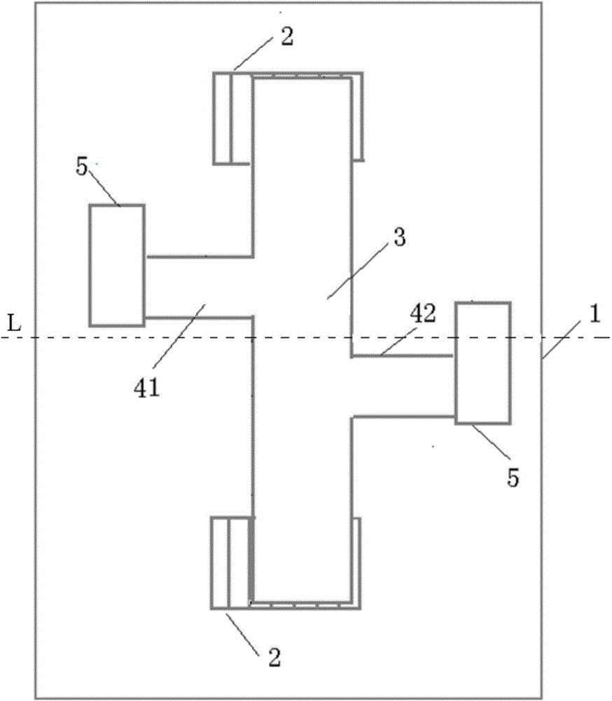
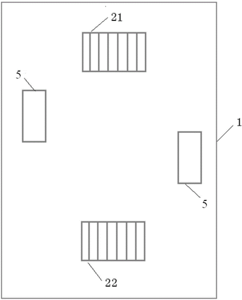
[0018] combine figure 1 with figure 2 As shown, a deflection capacitive surface micromachining residual stress test structure is characterized in that it includes a substrate 1, two lower plates 2 and an upper plate 3, a left beam 41, a right beam 42 and two anchor areas 5;

[0019] The lower plate 2 is deposited on the upper surface of the substrate 1; two anchor regions 5 are placed on the substrate 1;

[0020] The upper pole plate 3 is suspended above the lower pole plate 2; the left crossbeam 41 and the right crossbeam 42 are identical, are respectively located on both sides of the transverse central axis L of the upper pole plate 3, and are at the same distance from the central axis L; in this example The left side is high and the right side is low. In practice, as long as the distance between the two beams and the central axis L is equal. The right side of t...


PUM


Abstract

The invention discloses a test structure of micro-machining residual stress of a deflection capacitive surface. The test structure comprises a substrate, two lower electrode plates, an upper electrode plate, a left beam, a right beam and two anchoring zone. The lower electrode plates are deposited on the upper surface of the substrate, and the two anchoring zones are arranged on the substrate. The upper electrode plate is arranged above the lower electrode plates in a suspended mode, and the left beam and the right beam are identical and located on the two side of the horizontal central axis L of the upper electrode plate respectively, wherein the distance between the left beam and the central axis L is equal to that between the right beam and the central axis L. The right side of the left beam is connected with the left side of the upper electrode plate, and the left side of the left beam is fixed on the side face of one anchoring zone. The left side of the right beam is connected with the right side of the upper electrode plate, and the right side of the right beam is fixed on the side face of the other anchoring zone. The upper electrode plate, the left beam and the right beam are located in the same plane. The test structure is simple and easy to process, and in addition, test equipment is simple and high in precision. The measuring precision can be improved by increasing the area of the upper electrode plate and the area of the lower electrode plates in the test structure, and in addition, with the method for rotating the upper electrode plate in the test structure, a larger capacitance variation can be more easily obtained compared with a horizontally-moving method.

Description

technical field [0001] The invention relates to the field of surface micromachining residual stress testing, in particular to a deflection capacitive surface micromachining residual stress testing structure. Background technique [0002] MEMS is the abbreviation of Micro-Electro-Mechanical Systems (Micro-Electro-Mechanical Systems). MEMS organically combines electronic technology with mechanical properties, and can simultaneously realize physical, chemical, biological and other functions through the movement of the suspended structure. There are many processing methods for MEMS, and the surface micromachining process is one of the commonly used methods. The micromechanical structure is produced by continuously growing functional layers, structural layers, and sacrificial layers on silicon wafers, and selective etching is used to remove the structural layer. sacrificial layer, resulting in microstructures suspended near the substrate surface. [0003] However, residual stre...

Claims


Application Information

Patent Timeline
Patent Type & Authority Applications(China)
IPC IPC(8): G01L1/14
Inventor 唐洁影王磊蒋明霞
Owner SOUTHEAST UNIV
Learn More