Phase compound excitation electric generator

A generator and reactance technology, applied in the direction of synchronous generators, magnetic circuit static parts, magnetic circuit shape/style/structure, etc., can solve the problems of long production process cycle, affecting productivity, large consumption of materials, etc., and achieve weight Lightweight, easy maintenance, and effective use of materials

Inactive Publication Date: 2014-02-26
GUANGXI LUZHOU MACHINERY MFG
View PDF5 Cites 1 Cited by
  • Summary
  • Abstract
  • Description
  • Claims
  • Application Information

AI Technical Summary

Problems solved by technology

[0003] Although the existing phase-compound excitation generators have a certain automatic excitation function and automatically adjust the output voltage of the generator to make the voltage output constant, the linear reactor and the converter must use two sets of iron cores that are close to the same volume. And winding, the consumption of materials is large, and the production process cycle is also long, which affects the improvement of productivity

Method used


Image

  • Phase compound excitation electric generator
  • Phase compound excitation electric generator
  • Phase compound excitation electric generator

Examples


Embodiment 1

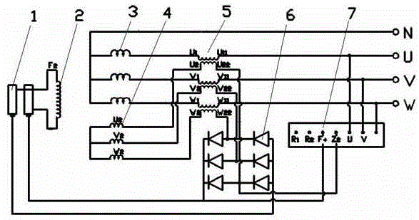
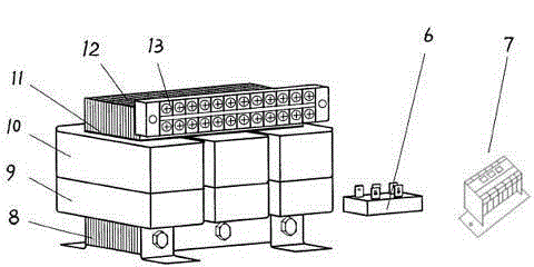
[0034] like figure 1 and figure 2As shown, when the phase compound excitation generator is made into a three-phase synchronous generator, the composite reactance converter is composed of a "mountain" shaped iron core 8, three The three-phase primary winding 9, the three-phase secondary winding 10, the upper yoke core 12 matched with the "mountain"-shaped iron core and the three-phase terminal block 13, the three-phase stator auxiliary winding 4 The phase sequence is the same as that of the three-phase stator main winding 3, and the phase lags behind the stator main winding 3. The three-phase line ends of the stator main winding 3 are connected to the corresponding three-phase ends of the primary winding 9 of the composite structure, and the primary winding 9 The three-phase starting end is the output load end, and the three-phase wire end of the stator secondary winding 4 should be connected with the corresponding three-phase starting end of the secondary winding 10, and the...

Embodiment 2

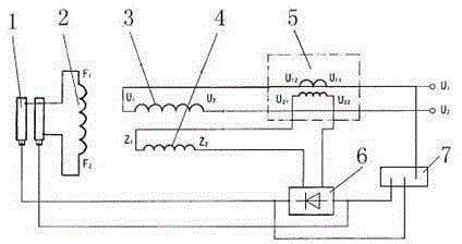
[0043] like image 3 and Figure 4 As shown, when the phase compound excitation generator is made into a single-phase generator, the compound reactance converter is composed of a "U"-shaped iron core 8 installed on the chassis, a single-phase primary Winding 9, single-phase secondary winding 10, upper yoke iron core 12 matched with "U"-shaped iron core 8 and single-phase terminal block 13, the single-phase stator main winding 3 The wire end is connected to the end of the primary winding 9, the beginning of the primary winding 9 is the output load end, the two ends of the single-phase stator secondary winding 4 are connected to the beginning of the secondary winding 10, and the end of the secondary winding 10 is connected to the single-phase rectifier bridge group 6, the other end of the rectifier bridge group 6 is connected to the collector ring 14, and the automatic voltage regulator 7 is connected to the single-phase rectifier bridge group 6, the primary winding 9 and the c...


PUM


Abstract

The invention discloses a phase compound excitation electric generator which comprises a rotor, a stator, a collecting ring, a rotor winding, a stator main winding, a stator auxiliary winding, a composite reactance converter, a rectifier bridge set and an automatic voltage regulator. A phase compound excitation device is composed of the composite reactance converter, the rectifier bridge set and the automatic voltage regulator. The composite reactance converter is composed of an iron core, a primary winding, a secondary winding, an upper yoke iron core and a wiring terminal block which are arranged on a bottom frame. The wire end of the stator main winding is connected with the tail end of the primary winding, the starting end of the primary winding is an output load end, the wire end of the stator auxiliary winding is connected with the starting end of the secondary winding, the tail end of the secondary winding is connected with one end of the rectifier bridge set, the other end of the rectifier bridge set is connected with the collecting ring, and the automatic voltage regulator is connected with the rectifier bridge set, the primary winding and the collecting ring at the same time. The phase compound excitation electric generator has the advantages of being little in material consumption, small in size, low in weight, and wide in application range.

Description

technical field [0001] The invention relates to a generator, in particular to a phase compound excitation generator. Background technique [0002] Generators are divided into two categories: DC generators and AC generators. The latter can be divided into synchronous generators and asynchronous generators. The most commonly used in modern power stations are synchronous generators. Generators are usually composed of stators, rotors, end covers, bearings and other components. The stator is composed of stator core, wire wrap winding, frame and other structural parts that fix these parts. The rotor is composed of rotor core (or magnetic pole, magnetic yoke) winding, guard ring, center ring, slip ring, fan and shaft and other components. The stator and the rotor of the generator are connected and assembled by the bearing and the end cover, so that the rotor can rotate in the stator and do the movement of cutting the magnetic force line, thereby generating an induced potent...

Claims


Application Information

Patent Timeline
Patent Type & Authority Applications(China)
IPC IPC(8): H02K19/28H02K19/36H02K1/26H02K1/24H02K1/32H02K1/16
Inventor 朱祖锋李庚荣梁海著
Owner GUANGXI LUZHOU MACHINERY MFG
Why Eureka
Try Eureka