Dead zone compensation control method and system thereof

A dead zone compensation and control method technology, applied in the field of electronics, can solve the problems of power supply and other electrical appliances, power supply pollution, compressor phase current distortion, power supply pollution and other problems

Active Publication Date: 2014-02-26
SICHUAN CHANGHONG ELECTRIC CO LTD
View PDF3 Cites 6 Cited by
  • Summary
  • Abstract
  • Description
  • Claims
  • Application Information

AI Technical Summary

Problems solved by technology

[0006] This application provides a dead zone compensation control method and system, which solves the technical problem in the prior art that the phase current of the compressor is distorted due to inaccurate dead zone compensation, and the power supply of the power

Method used


Image

  • Dead zone compensation control method and system thereof
  • Dead zone compensation control method and system thereof
  • Dead zone compensation control method and system thereof

Examples


Embodiment Construction

[0041] The embodiment of the present application provides a dead zone compensation control method and system, which solves the technical problem in the prior art that the phase current of the compressor is distorted due to inaccurate dead zone compensation, and the power supply of the power supply and other electrical appliances is polluted. , to improve the accuracy of dead zone compensation, reduce the distortion of the current, and reduce the technical effects of power supply and other electrical power supply pollution.

[0042] The technical solution in the embodiment of the present application is to solve the above-mentioned technical problems, and the general idea is as follows:

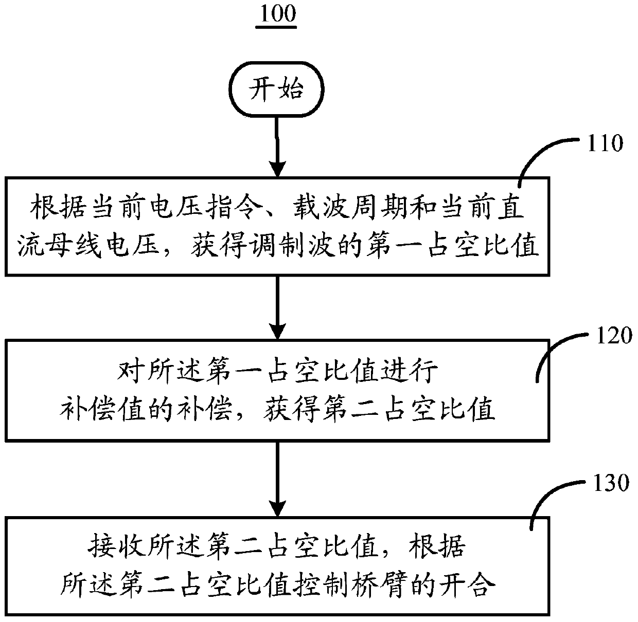
[0043] A dead zone compensation control method, the dead zone compensation control method comprising:

[0044] According to the current voltage command, the carrier cycle and the current DC bus voltage, obtain the first duty cycle value of the modulated wave;

[0045] Compensating the compensa...


PUM


Abstract

The invention discloses a dead zone compensation control method and a system thereof. The dead zone compensation control method comprises the following steps of acquiring a first duty ratio of a modulating wave according to a current voltage instruction, a carrier wave period and a current direct current bus voltage; carrying out compensation of a compensation value on the first duty ratio so that a second duty ratio is acquired, wherein the compensation value is decided by a current instruction; the current instruction corresponds to the current voltage instruction; receiving the second duty ratio and controlling opening and closing of a bridge arm according to the second duty ratio.

Description

technical field [0001] The invention relates to the field of electronic technology, in particular to a dead zone compensation control method and system. Background technique [0002] Each of the three phases U, V, and W in the hardware circuit of the frequency conversion controller includes two upper and lower complementary bridge arms (ie IGBT, Insulated Gate Bipolar Transistor, Chinese full name: Insulated Gate Bipolar Transistor). Each bridge arm is a composite fully-controlled voltage-driven power semiconductor device composed of BJT (bipolar transistor) and MOS (insulated gate field effect transistor). The upper and lower bridge arms are strictly turned on and off in turn. [0003] But the actual situation is that it takes a certain amount of time for each device to turn on and off, especially the turn-off time is longer than the turn-on time. During the turn-off process, if the cut-off device is turned on immediately, it will inevitably cause a short circuit of the br...

Claims


Application Information

Patent Timeline
IPC IPC(8): H02M1/088
Inventor 钟明陈跃凃小平刘启武
Owner SICHUAN CHANGHONG ELECTRIC CO LTD
Why Eureka
Try Eureka