Power taking device based on non-closed current transformer and control method thereof

A technology of current transformer and power taking device, applied in the field of power taking device based on non-closed current transformer, can solve the problem of increasing the output impedance of the current transformer, large parallel capacitance and volume, low output voltage and power, etc. problems, to avoid saturation and heat generation, improve stability, and prolong service life.

Active Publication Date: 2014-02-26
ZHEJIANG TUWEI ELECTRICITY TECH +1
View PDF5 Cites 9 Cited by
  • Summary
  • Abstract
  • Description
  • Claims
  • Application Information

AI Technical Summary

Problems solved by technology

However, there are two problems with this method: first, the capacitance of the parallel capacitor must be strictly matched with the excitation inductance of the current transformer. When the inductance of the excitation inductance changes, this method cannot achieve the effect of significantly increasing the output impedance of the current transformer ; Second, the parallel capacitor must use a non-polar capacitor. When the excitation inductance is small, the capacitanc

Method used


Image

  • Power taking device based on non-closed current transformer and control method thereof
  • Power taking device based on non-closed current transformer and control method thereof
  • Power taking device based on non-closed current transformer and control method thereof

Examples


Embodiment approach

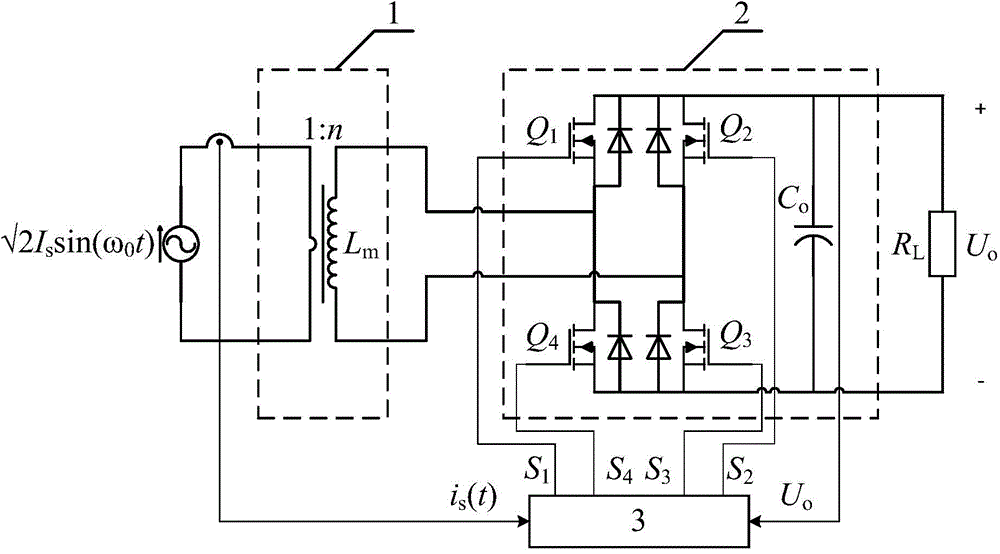
[0079] As a further improvement of the above-mentioned power-taking control method, when the parameters of the transmission line, power-taking device, load, etc. change, the switching tube control unit can implement another power-taking method, by adjusting d maintain the output voltage obtained by U o constant. Accordingly, in each cycle of the alternating current of the transmission line, the switch tube control unit collects the DC output voltage of the active rectification filter unit and the polarity of the transmission line current, and calculates the next power transmission line according to the collected voltage. t of the alternating current cycle of the line d, and will be executed after the polarity of the transmission line current is changed from negative to positive next time. As another implementation, the above maintenance U o The constant power-taking method includes the following steps:

[0080] (a) The DC output voltage reference value U of the given activ...


PUM


Abstract

The invention discloses a power taking device based on a non-closed current transformer. The power taking device comprises the current transformer, a rectifying unit and a control unit. A diode rectifying filter unit of a traditional power taking device is replaced by an active rectifying filter unit completely formed by switching tubes. When a current of a transmission line is small, even if the power taking device is matched with a current transformer with a non-closed magnetic circuit and small magnetic inductance in use, enough output voltage and power also can be obtained and supplied to a load, so that the volume and manufacturing cost of the current transformer are reduced. When the current of the transmission line is large, the power taking device can avoid obtaining overlarge output voltage and power. The invention further discloses a control method of the power taking device. By means of the control method of the power taking device, when parameters of the transmission line, the power taking device, the load and the like change, direct current output voltage obtained by the power taking device is kept constant, so that power supplying stability of the power taking device is improved.

Description

technical field [0001] The invention belongs to the technical field of power electronics, and in particular relates to a power-taking device based on a non-closed current transformer and a control method thereof. Background technique [0002] In order to improve the safety and reliability of high-voltage transmission lines, online monitoring of their operating conditions is required, but it is very inconvenient to supply power to these monitoring equipment placed around the transmission lines, such as in the field or underground, generally cannot provide 220V AC mains power , and the stability and maintenance-free of photovoltaic panels or batteries are poor. Only the use of current transformers to directly obtain power from high-voltage transmission lines through electromagnetic induction is a relatively safe, stable, and long-term maintenance-free power supply method. However, the current of the high-voltage transmission line fluctuates greatly. The traditional current tr...

Claims


Application Information

Patent Timeline
IPC IPC(8): H02M7/217
CPCH02M7/219Y02B70/10
Inventor 吴建德王智博骆定华吴成才何湘宁
Owner ZHEJIANG TUWEI ELECTRICITY TECH
Why Eureka
Try Eureka