Concentrating photovoltaic and photo-thermal composite power generation system

A power generation system and concentrating photovoltaic technology, applied in the field of solar energy utilization, can solve the problem of ineffective utilization of the waste heat of photovoltaic power generation, and achieve the effects of improving system efficiency and economy, reducing energy loss, and alleviating the problem of peak regulation

Active Publication Date: 2014-02-26
恒基能脉新能源科技有限公司
View PDF9 Cites 14 Cited by
  • Summary
  • Abstract
  • Description
  • Claims
  • Application Information

AI Technical Summary

Problems solved by technology

In this way, the combination of photovoltaic, light and heat is completely based on the distribution of light, and the waste heat of photovoltaic power generation has not been effectively utilized.

Method used


Image

  • Concentrating photovoltaic and photo-thermal composite power generation system
  • Concentrating photovoltaic and photo-thermal composite power generation system
  • Concentrating photovoltaic and photo-thermal composite power generation system

Examples


Embodiment 1

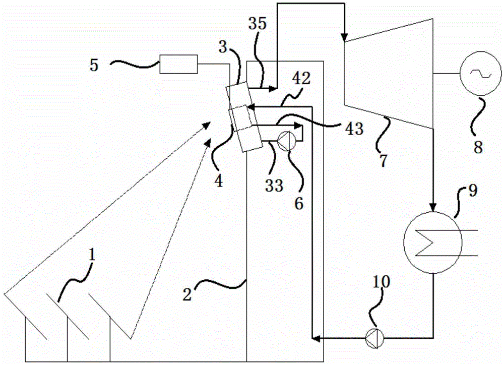
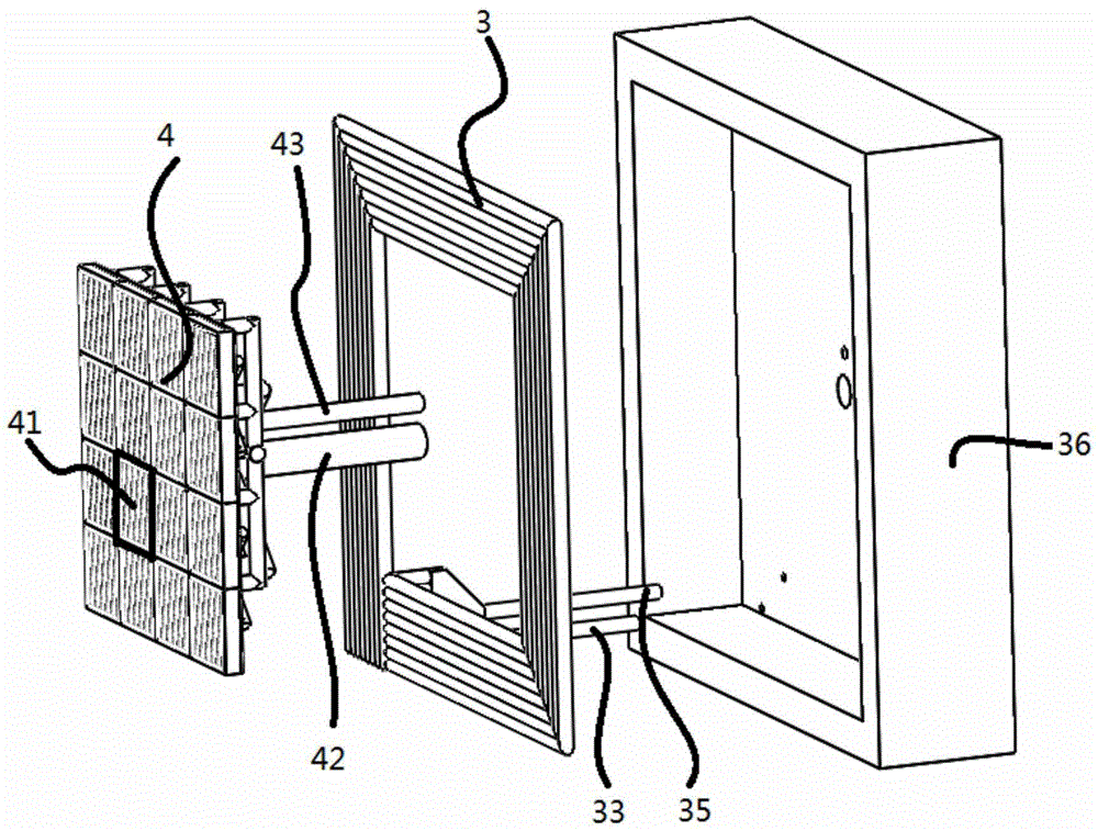
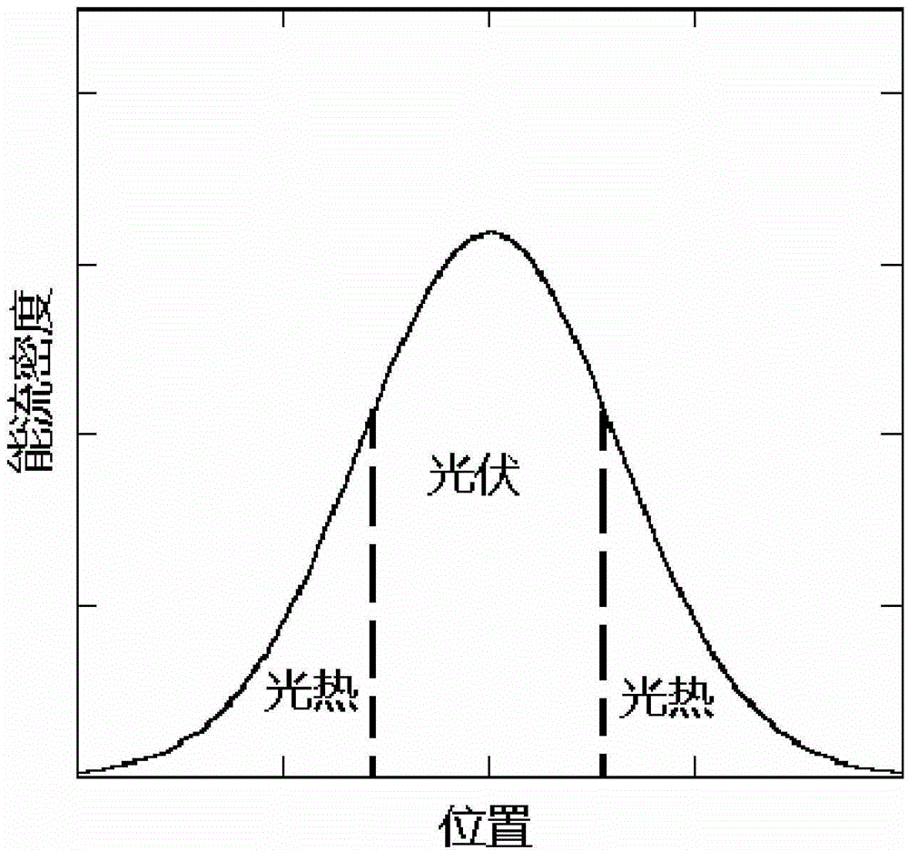
[0044] see figure 1 As shown, a concentrating photovoltaic photothermal composite power generation system based on dense array cells includes a tracking concentrating system composed of heliostat 1 and receiving tower 2, a photovoltaic photothermal module and its thermal cycle part. The photovoltaic photothermal module also includes a dense array battery module 4, a heat absorber module 3 and their insulation layer 36, a connecting circuit and a supporting structure, and the heat absorber module 3 is arranged on the periphery of the dense array battery module 4 to adapt to solar energy concentration. Spot energy flux density distribution behind the light (see image 3 shown), match the part with higher energy flux density in the center of the spot with the surface of the dense array battery module 4, and match the part with lower energy flux density at the edge of the spot with the surface of the heat sink module 3. see figure 2 As shown, an insulating layer 36 is arranged ...

Embodiment 2

[0055] The shapes of the heat absorber module 3 and the dense array battery module 4 of this embodiment are different from those of the first embodiment, and the other system components and connection methods are the same as those of the first embodiment.

[0056] see Figure 11 As shown, in this embodiment, the photovoltaic photothermal module is arranged in a circular shape according to the characteristics of the light spot, wherein the annular heat absorber module 3 arranged outside is composed of a circular row of pipes 37 wound into a circle, and between the row of pipes It can be connected in series or in parallel; the dense array battery module 4 is composed of a circular CPV sub-module 47 and a plurality of fan-shaped CPV sub-modules 46 .

Embodiment 3

[0058] see Figure 12As shown, in this embodiment, the photovoltaic photothermal module includes a dense array battery module 4 and a heat absorber module 3 , and the heat absorber module 3 is arranged on the periphery of the dense array battery module 4 . There is also a secondary concentrator (SC) 11 arranged around the photovoltaic photothermal module. The secondary concentrator 11 collects and projects the energy in the area with a low spot energy flux density on the photovoltaic photothermal module. Its shape can be composite Parabolic light funnel and conical light funnel, etc. An SC cooling tube bundle 12 is also installed outside the secondary concentrator 11 to prevent the surface temperature of the secondary concentrator 11 from being too high. The cooling medium flows into the dense array battery module 4 from the inlet main pipe 42 of the CPV cooling system. After cooling the battery array, it is heated and flows out from the outlet main pipe 43 of the CPV cooling...


PUM


Abstract

The invention discloses a concentrating photovoltaic and photo-thermal composite power generation system, and belongs to the technical field of solar energy utilization. The system comprises a tracking concentrating system, a photovoltaic and photo-thermal module and a thermal cycle portion. The photovoltaic and photo-thermal module comprises a dense array battery module, a heat absorber module, a heat preservation layer, a connecting loop and a supporting structure. The heat absorber module is arranged on the periphery of the dense array battery module. The portion with the higher energy flux density in the center of a concentrating facula is projected to the surface of the dense array battery module, and the other portions are projected to the surface of the heat absorber module. After cooling liquid cools the dense array battery module, the temperature of the cooling liquid rises, the cooling liquid is used as a heat absorption working medium to be pumped into the heat absorber module to continuously absorb energy, steam with the certain temperature is generated, and electricity is generated through a thermal cycle. A secondary concentrator module can also be arranged on the periphery of the photovoltaic and photo-thermal module, and the optical characteristics of the system can be further improved by means of the secondary concentrator module. According to the concentrating photovoltaic and photo-thermal composite power generation system, the efficiency and economical performance of photovoltaic and photo-thermal power generation can be improved, and impact, caused by photovoltaic power generation, on a power grid can also be weakened.

Description

technical field [0001] The invention relates to the technical field of solar energy utilization, in particular to a novel solar concentrated photovoltaic photothermal composite power generation system. Background technique [0002] Solar energy is an important way to utilize renewable energy. There are usually two ways of solar power generation—photovoltaic power generation and photothermal power generation. The photovoltaic power generation system uses the photovoltaic effect of semiconductor materials to generate electricity, which has the advantages of high efficiency and simple and flexible system. However, due to the unstable output of the photovoltaic system, it will have a certain impact on the power grid. The solar thermal power generation system uses concentrators and heat absorbers to convert solar radiation energy into heat energy, and generates power through traditional thermal cycle methods. It has the characteristics of stable power generation and is suitable f...

Claims


Application Information

Patent Timeline
Patent Type & Authority Applications(China)
IPC IPC(8): H02S10/10H02S30/10H02S40/42F03G6/06
CPCY02E10/46Y02E10/50
Inventor 巨星徐超杜小泽杨勇平王志峰
Owner 恒基能脉新能源科技有限公司
Why Eureka
Try Eureka