Processing method of baseplate bunching groove for electric pulse processing
A processing method and base plate technology, which is applied in the processing field of grouped grooves of the base plate for electric pulse processing, can solve the problems of failing to meet tolerance requirements, low processing accuracy, and low processing efficiency, and avoid the influence of human factors and the difficulty of processing The effect of reducing and improving the pass rate
- Summary
- Abstract
- Description
- Claims
- Application Information
AI Technical Summary
Problems solved by technology
Method used
Image

Examples
Embodiment Construction
[0020] The present invention will be further described in detail below in conjunction with the accompanying drawings and specific embodiments.
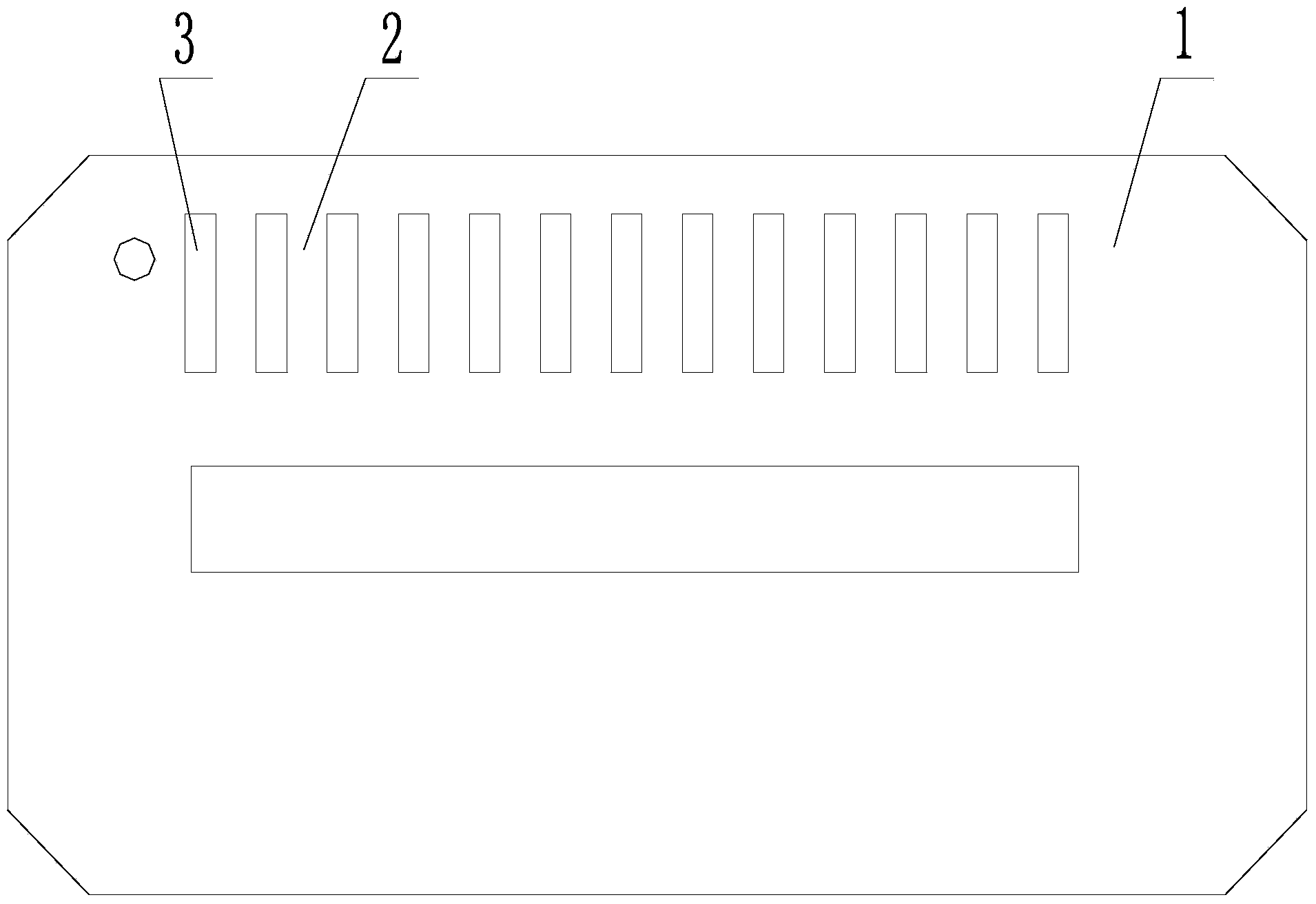
[0021] Such as figure 1 As shown, on the bottom plate 1 that needs to be processed in this embodiment, there are 13 protrusions 3, and the protrusions 3 are separated from each other by 12 parts mounting grooves 2. The groove width of the parts mounting groove 2 is 6mm, and the groove width tolerance is the same as The pitch tolerance is ±0.01mm. The machine tool is a CNC slow-moving wire machine tool.
[0022] Adopting the processing method of grouping grooves on the base plate for electric pulse processing to process the parts mounting groove 2 on the base plate 1, specifically includes the following steps:
[0023] Step 1: Before processing the bottom plate 1, first open the workbench baffle of the slow wire-feeding machine tool, and clean the workbench surface to ensure that there is no dirt on the workbench surface, so as to av...
PUM
 Abstract
Description
Claims
Application Information
 - Generate Ideas
- Intellectual Property
- Life Sciences
- Materials
- Tech Scout
- Unparalleled Data Quality
- Higher Quality Content
- 60% Fewer Hallucinations
Browse by: Latest US Patents, China's latest patents, Technical Efficacy Thesaurus, Application Domain, Technology Topic, Popular Technical Reports.
© 2025 PatSnap. All rights reserved.Legal|Privacy policy|Modern Slavery Act Transparency Statement|Sitemap|About US| Contact US: help@patsnap.com