
Bionic flapping-wing machine with double-section main wings

A flapping-wing aircraft and airframe technology, applied in the field of aircraft, can solve the problems of unequal lateral force on the fuselage, small net lift of the wing, and insufficient flexibility, etc., to achieve increased flight speed and air time, simple and compact structure, and directional control sensitive effect

Inactive Publication Date: 2014-03-05
CIVIL AVIATION UNIV OF CHINA
View PDF6 Cites 27 Cited by
  • Summary
  • Abstract
  • Description
  • Claims
  • Application Information

AI Technical Summary

Problems solved by technology

[0003] At present, the existing bionic flapping wing aircraft has the following problems: ①The upper driving mechanism adopts a single crank and double rocker mechanism. Due to the asymmetry of the movement of the left and right wings, the lateral force of the fuselage is unequal, which affects the flight. stability and security
②The wing can only flap up and down simply, and the wing resistance is large when flapping upwards, resulting in a small net lift generated by the wing in a flapping cycle, and the flapping wing aircraft stays in the air for a short time and at a low flying speed
③The steering control of the orthopter adopts the way of steering gear to control the rudder, which is not flexible enough and has a single function

Method used


Image

  • Bionic flapping-wing machine with double-section main wings
  • Bionic flapping-wing machine with double-section main wings
  • Bionic flapping-wing machine with double-section main wings

Examples


Embodiment Construction

[0019] The two-section main-wing bionic flapper aircraft provided by the present invention will be described in detail below in conjunction with the accompanying drawings and specific embodiments.

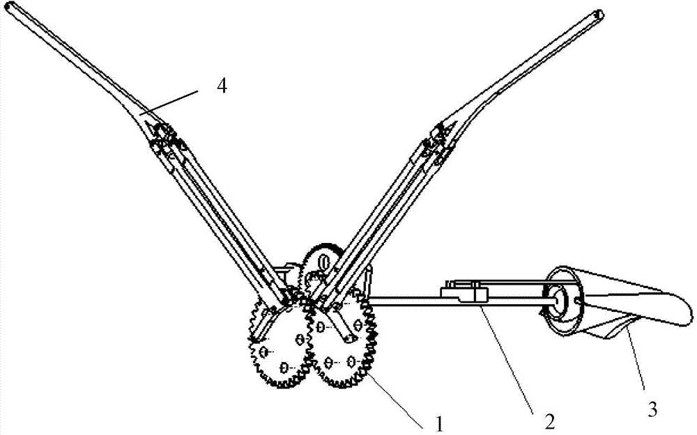
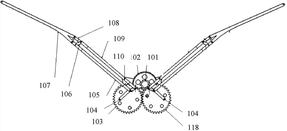
[0020] Such as figure 1 — Figure 6 As shown, the double-section main wing bionic flapping wing aircraft provided by the present invention includes a drive mechanism 1, a main support 2, an empennage mechanism 3, a double-section flapping wing mechanism 4 and two steering gears 308; wherein the drive mechanism 1 is connected to the front of the main support 2 At the front end, the empennage mechanism 3 is connected to the rear end of the main bracket 2, and the double-section flapping wing mechanism 4 is connected to the driving mechanism 1; two steering gears 308 are installed on the main bracket 2;

[0021] The drive mechanism 1 includes a quadrilateral body 5, a micro DC motor 119, a gear reduction mechanism and two connecting rods 104; wherein the quadrilateral body 5 is a ver...


PUM


Abstract

The invention discloses a bionic flapping-wing machine with double-section main wings. The bionic flapping-wing machine comprises a driving mechanism, a main bracket, a tail-wing mechanism, a double-section flapping-wing mechanism and two steering machines, wherein the driving mechanism is connected with the front end of the main bracket; the tail-wing mechanism is connected with the rear end of the main bracket; the double-section flapping-wing mechanism is connected to the driving mechanism; the two steering machines are arranged on the main bracket. The bionic flapping-wing machine disclosed by the invention has the following beneficial effects that the structure is simple and compact, the flapping-wing movement with complete symmetry can be realized, the flapping-wing machine can fly like a bird by adopting the double-section flapping-wing mechanism, due to the foldable wings, the resistance of the wings can be small in upwards flapping and the wingspan area can be the largest in downwards flapping, so that large lifting force is generated, and the flying speed and the hang time are increased. In addition, a spherical pair is adopted for connection with the tail-wing mechanism, the direction control of the flapping-wing machine is sensitive and the flapping-wing machine can imitate the flying of the bird. Furthermore, the bionic flapping-wing machine can be applied to the fields of bird repelling of an airport, monitoring, intelligence gathering, disaster rescuing and searching and the like.

Description

technical field [0001] The invention belongs to the technical field of aircraft, in particular to a bionic flapping wing aircraft with two main wings. Background technique [0002] The bionic orthopter is a new concept aircraft that can imitate the flight of birds or insects. Compared with traditional fixed-wing and rotary-wing aircraft, the bionic flapping-wing aircraft integrates the functions of lifting, hovering and propulsion into one flapping-wing system, and has the characteristics of compact structure, high aerodynamic efficiency and good maneuverability. In view of the fact that the bionic flapper has great advantages in military and civilian applications, the development of this device has become a new hot spot. [0003] At present, the existing bionic flapping wing aircraft has the following problems: ①The upper driving mechanism adopts a single crank and double rocker mechanism. Due to the asymmetry of the movement of the left and right wings, the lateral force ...

Claims


Application Information

Patent Timeline
IPC IPC(8): B64C33/02
Inventor 杨永刚谢友增
Owner CIVIL AVIATION UNIV OF CHINA
Learn More