A swing type cutting knife device
What is Al technical title?
Al technical title is built by PatSnap Al team. It summarizes the technical point description of the patent document.
A technology of swinging device and slitting knife, which is applied in the directions of transportation and packaging, sending objects, and thin material processing, etc., can solve the problems of deviation, shrinkage thickness of edge layer heat shrinkable film, uneven thickness of heat shrinkable film, etc. The problem of edge warping and the effect of improving the quality of product packaging
Active Publication Date: 2015-09-16
河南银金达新材料股份有限公司
View PDF8 Cites 0 Cited by
Summary
Abstract
Description
Claims
Application Information
AI Technical Summary
This helps you quickly interpret patents by identifying the three key elements:
Problems solved by technology
Method used
Benefits of technology
Problems solved by technology
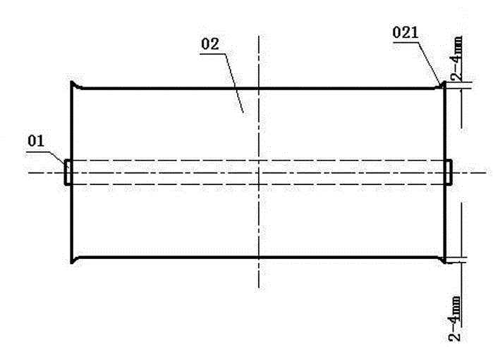
The warping edge 021 of the heat shrinkable film wound on the paper core 01 is generally 2-4mm wide. This warping will cause the heat shrinkable film to be inaccurate during printing, causing the problem of printing plate running, and making the later heat shrinkable film Can't print normally
[0003] The current slitting technology usually improves this situation by reducing the winding tension and pressure during slitting, but this method will lead to a decrease in the tightness of the film roll, resulting in the film being too loose and falling off the cylinder or running off. This adjustment method to reduce the tightness can not fundamentally solve the warping of the heat shrinkable film, but can only reduce the warping phenomenon
[0004] The root cause of the warping of the heat shrinkable film during slitting is that the thickness of the heat shrinkable film itself is not uniform, and the second is that the slitting blade rubs and heats up to the shrinkage temperature of the heat shrinkable film when cutting the heat shrinkable film, causing the edge layer to heat up. The shrink film shrinks and thickens, causing warping
Method used
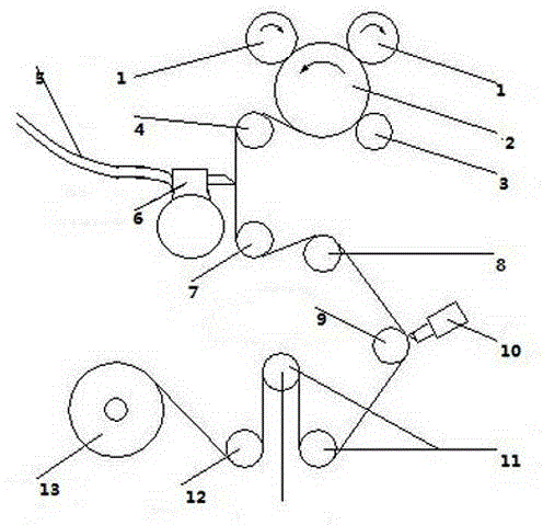
Image
Click on the blue label to locate the original text in one second.
Reading with bidirectional positioning of images and text.
Examples
Embodiment Construction
[0022] Such as figure 2 As shown, the present invention provides a swinging slitting knife device, including a winding shaft 1, fixed speed rollers 2, 3, positioning rollers 4, power rollers 8, detection rollers 9, CCD sensors 10, enabling rollers 11, rolling Composed of roller 12, unwinding and deviation correction actuator 13, and swing device. Among them, the winding shaft 1, the fixed speed roller 2, 3, the positioning roller 4, the power roller 8, the detection roller 9, the CCD sensor 10, the energizing roller 11, the flattening roller 12, and the unwinding and deviation correcting actuator 13 are sequentially connected. Swing device is connected with cutter arm fixed track 14, and cutting blade 15 is fixed on the cutter arm, and heat-shrinkable film 18 passes between cutting blade 15 and positioning roller 4,7 and cuts.
[0023] In order to improve the cutting efficiency, the number of cutting knives is 2-20. The preferred number of slitting blades is 6, 8 or 12, and...
PUM
Abstract
The invention provides a novel thermal contraction film slitting device of a swing structure. The slitting device comprises a rolling shaft, constant speed rollers, positioning rollers, a power roller, a detection roller, a CCD sensor, an enabling roller, a rolling-out roller, an unrolling and deviation rectification execution mechanism and a swing device. The rolling shaft, the constant speed rollers, the positioning roller (4), the power roller, the detection roller, the CCD sensor, the enabling roller, the rolling-out roller and the unrolling and deviation rectification execution mechanism are connected in sequence; the swing device comprises a driving system, a sleeve, a breather pipe, a cutting knife arm, slitting knife blades, a cutting knife arm fixing track and a cylinder, the slitting knife blades are fixed on the cutting knife arm which moves on the cutting knife arm fixing track, one end of the cutting knife arm fixing track is in sliding contact with the driving system of the swing device, and the other end of the cutting knife arm fixing track is connected with the cylinder; the driving system comprises a frequency converter, the frequency converter controls a servo motor and is combined with an eccentric wheel through a driving shaft, and when the eccentric wheel rotates, the cutting knife arm fixing track (14) making contact with the eccentric wheel does reciprocating motion because of changes of the rotation radius; a thermal contraction film penetrates through the slitting knife blades and is slit between the positioning rollers.
Description
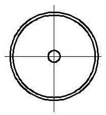
technical field [0001] The invention relates to the technical field of heat shrinkable film slitter mechanical equipment, in particular to a heat shrinkable film slitting device with a novel swing structure. Background technique [0002] In the prior art, the heat-shrinkable film slitting machine is mainly used to cut the heat-shrinkable film 02 into finished films of different widths. Existing slitting machine cutters mainly include square blades and round blades. These two blades can cut out very flat finished products according to the current technology when cutting common films. When cutting the heat shrinkable film 02, the edge warping phenomenon is very serious (see figure 1 and Figure 1a ). The warping edge 021 of the heat shrinkable film wound on the paper core 01 is generally 2-4mm wide. This warping will cause the heat shrinkable film to be inaccurate during printing, causing the problem of printing plate running, and making the later heat shrinkable film ...
Claims
Application Information
Patent Timeline
Application Date:The date an application was filed.
Publication Date:The date a patent or application was officially published.
First Publication Date:The earliest publication date of a patent with the same application number.
Issue Date:Publication date of the patent grant document.
PCT Entry Date:The Entry date of PCT National Phase.
Estimated Expiry Date:The statutory expiry date of a patent right according to the Patent Law, and it is the longest term of protection that the patent right can achieve without the termination of the patent right due to other reasons(Term extension factor has been taken into account ).
Invalid Date:Actual expiry date is based on effective date or publication date of legal transaction data of invalid patent.