Brake apparatus

A brake device and brake pad technology, which is applied in hoisting devices and other directions, can solve the problems of reducing braking force, braking failure, and increasing additional costs, and achieve the effects of improving mechanical performance, high braking precision, and improving stability

Active Publication Date: 2014-03-05
NINGBO ZHONGHUANG MACHINE & ELECTRICS
View PDF15 Cites 0 Cited by
  • Summary
  • Abstract
  • Description
  • Claims
  • Application Information

AI Technical Summary

Problems solved by technology

Because the brake device is located inside the drum, the volume of the drum is small, but there are the following disadvantages: because the brake pads are sleeved inside the drum, when the motor drives the drum to rotate, there is a relative rolling between the drum and the brake pads, which has a large friction force , causing the drum to generate a lot of heat, which affects the mechanical performance, and even the fiber rope on the drum surface will be fused when working for a long time; at the same time, the above-mentioned friction force consumes a considerable part of the power of the motor, which reduces the output power of the winch. Under the pressure of the rope, the inner wall of the drum will squeeze the brake pads, which will consume more motor power. In severe cases, it will cause the motor to stall and affect the performance of the whole machine; The friction area between the brake cones is small, resulting in poor braking performance; when braking, the two ends of the brake pads are squeezed by the conical truss and the brake cones respectively, which easily causes the brake pads to be squeezed and deformed to cause damage, and , During the braking process, the drum is not only under the pressure of the brake pads, but also the pressure of the rope, which may easily cause the deformation of the drum, reduce the friction area between the brake pads and the inner wall of the drum, and reduce the braking force. In severe cases, the brakes may even fail, causing accidents. the occurrence of the accident
[0004] Another example is the "Electric Winch Cone Brake Device" disclosed in Chinese Patent No. ZL200610052983.9. The brake device is arranged in the reduction box at the end of the drum. Although the problem of heat generated by the drum is relatively improved, the brake device is arranged on the drum end, resulting in an increase in the length and volume of the drum, which increases additional costs; when the lubricating oil in the reduction box leaks, the braking force will be greatly reduced, and in severe cases, the brake will slip or even fail; the brake The braking principle of the device is the same as that of the above-mentioned U.S. patent, that is, the conical disk of the inner hole cam and the brake cone simultaneously squeeze the brake pads, and squeeze the box of the reduction box through the brake pads to stop the roller from rotating. , there is also the corresponding defect of the above-mentioned US patent

Method used


Image

  • Brake apparatus
  • Brake apparatus
  • Brake apparatus

Examples


Embodiment Construction

[0025] The present invention will be further described below in conjunction with the accompanying drawings.

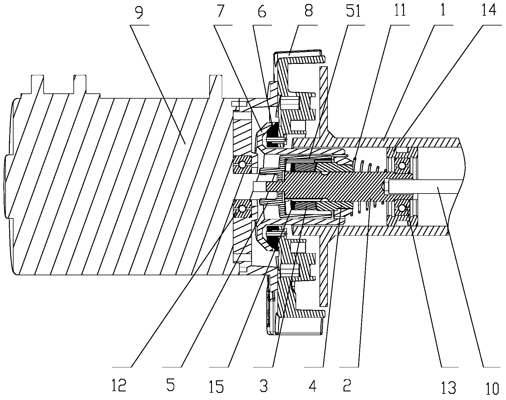
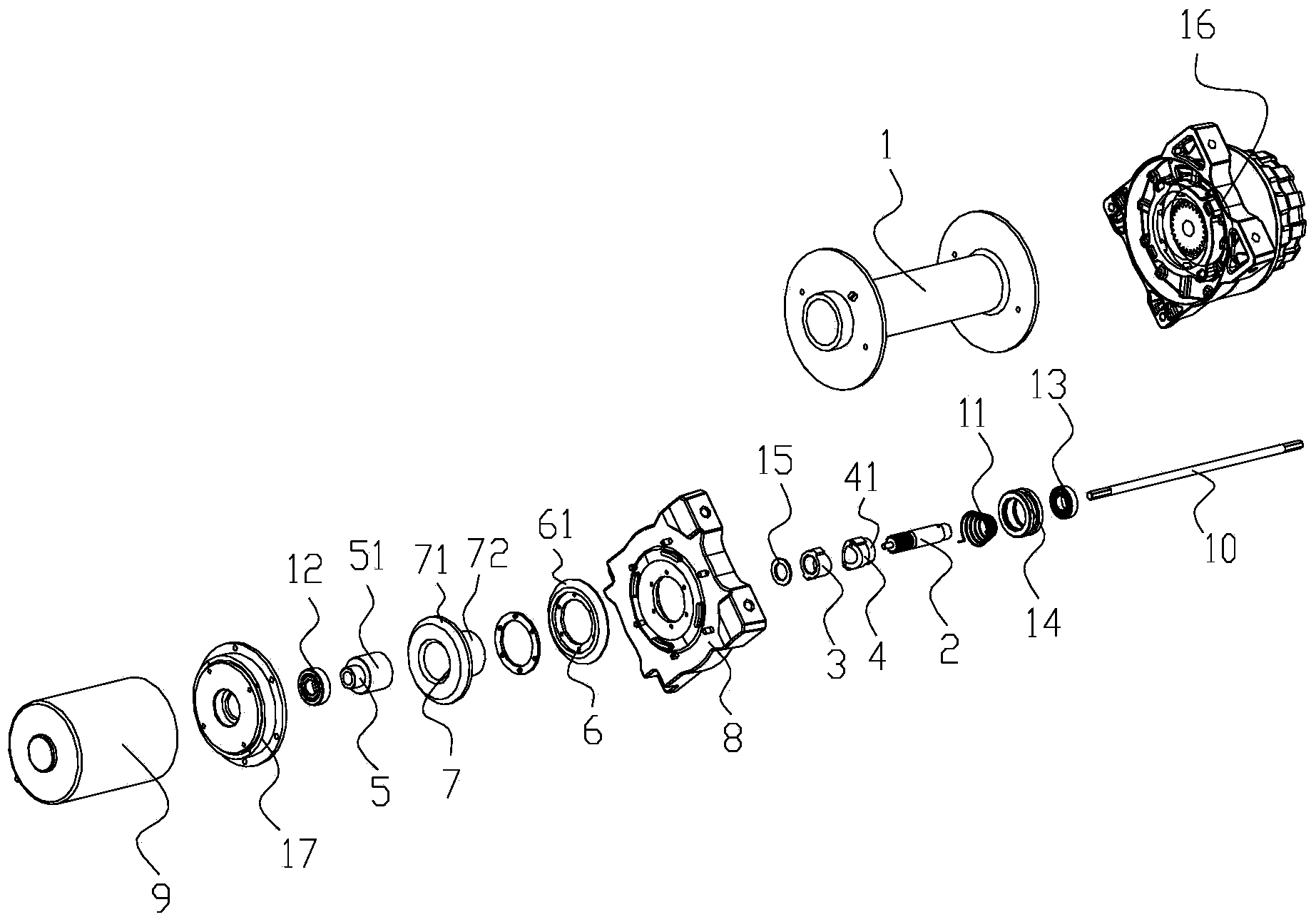
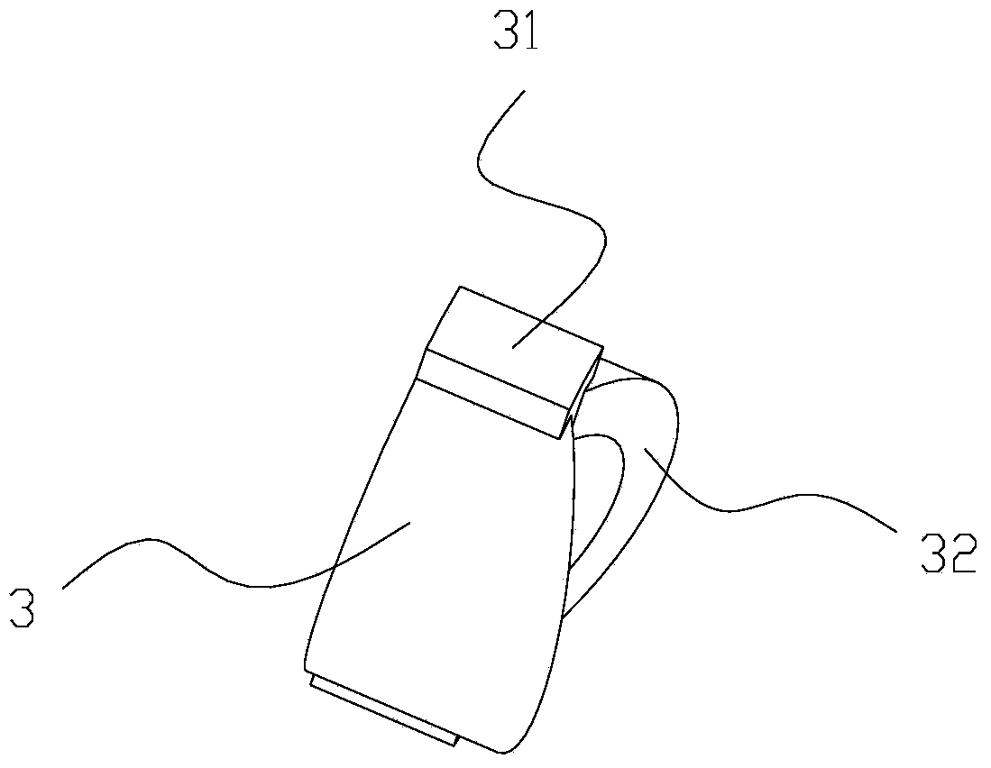
[0026] like Figure 1 to Figure 7 The shown brake device includes a drum 1, a spline shaft 2 inserted in the drum 1, an inner spline cam 3, an inner round hole cam 4, a coupling 5, a brake pad 6 and a brake pad 6. Cooperating brake cone disc 7.

[0027] The drum 1 is connected with the motor 9 through the bracket 8, the motor 9 provides power output, one end of the spline shaft 2 is inserted into the coupling 5, the other end of the spline shaft 2 is connected with the transmission shaft 10, and the transmission shaft 10 transmits power to the drum 1 through a reduction gear 16, and the coupling 5 is connected to the rotating shaft of the motor 9. The internal spline cam 3 is engaged and sleeved on the spline shaft 2, and the internal circular hole cam 4 is sleeved on the spline shaft 2 and is matched with the internal spline cam 3 correspondingly. The internal splin...


PUM


Abstract

The invention discloses a brake apparatus which comprises a rotary drum, a spline shaft, a cam with an internal spline, a cam with an internal circular hole, a coupling, a brake pad and a conical brake disc. The spline shaft is inserted into the rotary drum, the conical brake disc is matched with the brake pad, the rotary drum is connected with a motor by a support, the brake pad is fixedly arranged on the support, a conical surface is arranged at the peripheral edge of the brake pad, the conical brake disc comprises a conical disc and a sleeve, the conical disc runs in with the conical surface, the sleeve is integrally connected with the conical disc, one end of the sleeve is positioned in the rotary drum and is fixedly connected with the cam with the internal circular hole, a tower torsion spring is arranged at the tail end of the spline shaft, and two ends of the tower torsion spring are respectively connected with the spline shaft and the sleeve. The brake apparatus has the advantages that the rotary drum is small in size and low in cost; the brake apparatus is high in brake precision, and the brake stability can be improved; the problem that an existing rotary drum generates heat in no-load states can be effectively solved, and accordingly the mechanical performance of the brake apparatus can be improved.

Description

technical field [0001] The invention relates to the technical field of brakes, in particular to a brake device. Background technique [0002] The winch mainly utilizes the rotation of the drum to retract and pull the objects through the steel cable. When the motor stops working, it requires that the braking effect can be automatically generated at the moment the motor stops working, so as to avoid the slipping of the pulled objects and improve the operation safety. Therefore, the winch is also often installed on the front portion of the off-road vehicle for self-rescue use such as accidental slips and pits. [0003] Existing braking device such as U.S. Patent No. US005261646A, its structure comprises a drum, a section of spline shaft stretched and inserted in the drum, an internal spline cam, an inner circular hole cam, a shaft coupling, a brake pad and a brake pad cooperating with the brake pad. The roller is connected to the motor through a bracket, one end of the spline ...

Claims


Application Information

Patent Timeline
Patent Type & Authority Applications(China)
IPC IPC(8): B66D5/22
Inventor 曹科定毛秀挺陈光兵
Owner NINGBO ZHONGHUANG MACHINE & ELECTRICS
Why Eureka
Try Eureka