Low-temperature heat-insulation gas cylinder vacuumizing system

A vacuum pumping system, low temperature insulation technology, applied in fixed capacity gas storage tanks, gas/liquid distribution and storage, pressure vessels, etc., can solve the problems of long time, large area, small gas cylinder interlayer height, etc. Small, high efficiency, clean displacement effect

Inactive Publication Date: 2014-03-05
ZHANGJIAGANG FREE TRADE ZONE CHANGJIANG NEW ENERGY EQUIP
View PDF6 Cites 9 Cited by
  • Summary
  • Abstract
  • Description
  • Claims
  • Application Information

AI Technical Summary

Problems solved by technology

[0003] Ordinary low-temperature insulating gas cylinder vacuum system generally includes several gas cylinders installed in the vacuum heating room. The interlayer o

Method used


Image

  • Low-temperature heat-insulation gas cylinder vacuumizing system
  • Low-temperature heat-insulation gas cylinder vacuumizing system

Examples


Embodiment 1

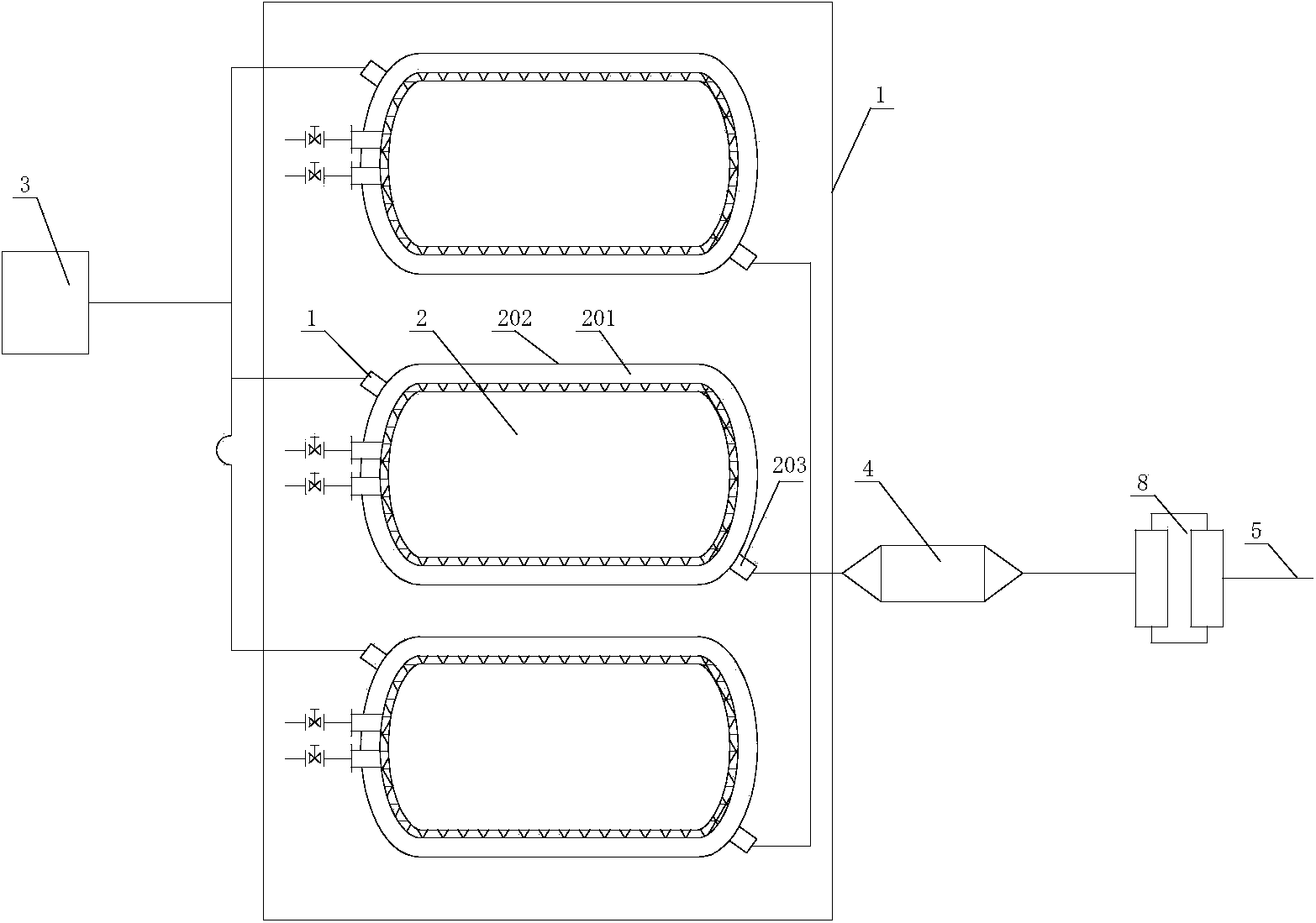
[0015] Example 1 as figure 1 As shown, a low-temperature heat-insulating gas cylinder vacuum system includes several gas cylinders 2 arranged in a vacuum heating room 1, the gas cylinder interlayer 201 communicates with the vacuum device 3, and the gas cylinder outer bladder 202 is provided with an inlet The air joint 203 and the air intake joint 203 communicate with the interlayer heating box 4, the dehumidifier 8, and the compressed air inlet pipe 5 sequentially through pipelines.

[0016] When vacuuming the low-temperature heat-insulating gas cylinder vacuum system as described above, firstly the compressed air enters the interlayer 201 of the gas cylinder from the dehumidifier 8 through the interlayer heating box 4 to heat the interlayer; then, the nitrogen gas is heated from the dehumidifier 8 through the interlayer The box 4 is heated and enters the gas cylinder interlayer 201 until the vacuum degree reaches the set value.

Embodiment 2

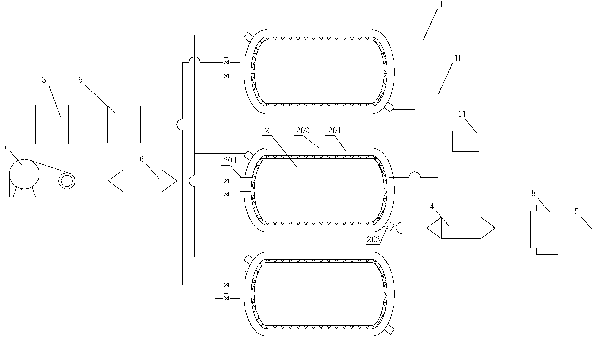
[0017] Example 2 as figure 2 As shown, a low-temperature heat-insulating gas cylinder vacuum system includes several gas cylinders 2 arranged in a vacuum heating room 1, the gas cylinder interlayer 201 communicates with the vacuum device 3, and the gas cylinder outer bladder 202 is provided with an inlet The air joint 203 and the air intake joint 203 communicate with the interlayer heating box 4 and the compressed air inlet pipe 5 sequentially through pipelines. The self-pressurizing port 204 of the gas cylinder liner is connected to the liner heating box 6 and the blower 7 in turn through pipelines. A dehumidifier 8 is provided between the interlayer heating box 4 and the compressed air inlet pipe 5 . A cold well 9 is provided between the gas cylinder interlayer 201 and the vacuum device 3 . The gas cylinders 2 are provided with a pressure-taking pipe 10 connecting the interlayers 201 of each gas cylinder, and a vacuum gauge 11 is provided on the pressure-taking pipe 10 . ...


PUM


Abstract

The invention discloses a low-temperature heat-insulation gas cylinder vacuumizing system. The low-temperature heat-insulation gas cylinder vacuumizing system comprises a plurality of gas cylinders arranged in a vacuum heating chamber, wherein the gas cylinder sandwich layers are communicated with a vacuumizing device, and air inlet joints are arranged on gas cylinder outer containers and are sequentially communicated with a sandwich layer heating tank, a dehumidifier and a compressed air inlet pipe through a pipeline.

Description

technical field [0001] The invention relates to a vacuum pumping system for a low-temperature heat-insulating gas cylinder. Background technique [0002] As a cryogenic pressure vessel, cryogenic insulated gas cylinders are mainly used to transport liquid oxygen, liquid nitrogen, liquid argon, and LNG gas, and can provide continuous use of gas. The inner liner is suspended in the outer liner through the support structures at both ends of the head and tail. The cylinder jacket is designed as a high-vacuum, multi-layer heat-insulating winding structure, and the inner tank is used to store cryogenic liquid. The outer wall of the inner tank is wrapped with multi-layer heat insulating material, which has super heat insulation performance. At the same time, the interlayer (between the inner tank and the outer tank) is evacuated to form a good thermal insulation system. [0003] Ordinary low-temperature insulating gas cylinder vacuum system generally includes several gas cylinde...

Claims


Application Information

Patent Timeline
IPC IPC(8): F17C1/12
Inventor 邵庆德陈永良
Owner ZHANGJIAGANG FREE TRADE ZONE CHANGJIANG NEW ENERGY EQUIP
Why Eureka
Try Eureka