
Combined type optical-electricity encoder with copper code disc

A photoelectric encoder and code disc technology, which is applied in the directions of instruments, converting sensor output, and using optical devices to transmit sensing components, can solve the problems of large system size, limited use range, and poor anti-interference performance, and achieves The production and assembly process is simple, the structure is simple, and the signal output is stable.

Inactive Publication Date: 2014-03-05
AUTOMATION RES & DESIGN INST OF METALLURGICAL IND
View PDF6 Cites 8 Cited by
  • Summary
  • Abstract
  • Description
  • Claims
  • Application Information

AI Technical Summary

Problems solved by technology

[0004] The purpose of the present invention is to provide a composite photoelectric encoder with a copper code disc, which uses a copper material engraved code disc to overcome the problems of large system structure size, poor anti-interference performance, low precision, and limited application range.

Method used


Image

  • Combined type optical-electricity encoder with copper code disc

Examples


Embodiment Construction

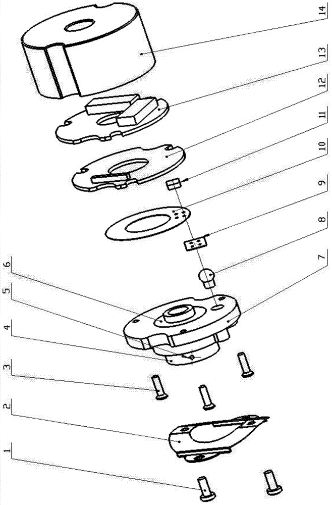
[0015] The following will be attached figure 1 The present invention is described in further detail.

[0016] The present invention includes mounting screw 1, fixed shrapnel card 2, positioning screw 3, connecting shaft sleeve 4, fastening screw 5, bearing 6, base 7, LED light source 8, grating ruler 9, copper code disc 10, photoelectric A receiving component 11, a signal conditioning circuit board 12, a signal amplifying circuit board 13, a casing 14, and the like. The shaft sleeve 4 and the fastening screw 5 are used together to tightly connect the motor shaft and the encoder, wherein the shaft sleeve 4 is connected to the base through the bearing 6 and the end of the shaft sleeve 4 far away from the motor shaft is tightly connected to the copper code disc 10 . The fixed shrapnel card 2 tightly connects the base 7 and the rear flange of the motor to prevent the radial displacement of the encoder. The grating ruler 9 is fixedly installed between the LED light source 8 and ...


PUM


Abstract

The invention relates to a combined type optical-electricity encoder with a copper code disc, and belongs to the technical field of electrified transmission detection. The combined type optical-electricity encoder with the copper code disc comprises a fixing elastic piece clamp, a fastening screw, a connecting shaft sleeve, a bearing, a base, an LED light source, a grating ruler, the copper code disc, an optical-electricity receiving component, a signal conditioning circuit board, a signal amplification circuit board, a shell and locating screws. A permanent magnet synchronous motor shaft and the connecting shaft sleeve are tightly connected through the fastening screw, the copper code disc is fixed at one end, far away from the motor shaft, of the connecting shaft sleeve, the LED light source is fixed in a light source hole of the base, and the grating ruler is arranged and fixed on the outer portion of the light source hole of the base. The optical-electricity receiving component is welded to the signal conditioning circuit board, and the signal conditioning circuit board, the signal amplification circuit board and the shell are arranged on the base in a matched mode through the locating screws. The base is fastened with the outer ring of the bearing, and the inner ring of the bearing is fastened with the outer ring of the connecting shaft sleeve. The combined type optical-electricity encoder with the copper code disc has the advantages of being simple and compact in structure, low in cost and easy to mount and use. A rotor magnetic pole position signal 'U' or 'V' or 'W' and a rotor displacement signal 'A' or 'B' and a correction signal 'Z' in an alternating current servo system can be provided simultaneously, wherein the rotor magnetic pole position signal 'U' or 'V' or 'W' and the rotor displacement signal 'A' or 'B' are needed for controlling a permanent magnet synchronous motor, and the correction signal 'Z' is used for eliminating accumulated errors.

Description

technical field [0001] The invention belongs to the technical field of electric transmission detection, and in particular relates to a copper code disc composite photoelectric encoder, which is suitable for servo systems and automatic control systems as detection elements and feedback elements, and particularly relates to permanent magnet synchronous motor rotors in AC servo systems Accurate detection of pole position and rotor speed, specifically in the field of AC drives. Background technique [0002] The working principle of the photoelectric encoder is to convert the mechanical geometric displacement on the receiving shaft into pulse or digital quantity through photoelectric conversion. As a sensor in the field of electric transmission, it has gradually expanded from the national defense and military industry to the civilian industry. For example, the application on military radar, artillery, and aerospace vehicles is extended to the application on CNC machine tools, ro...

Claims


Application Information

Patent Timeline
Patent Type & Authority Applications(China)
IPC IPC(8): G01D5/347G01D5/38
Inventor 宋词王东文陈雪松佟宁泽侯竑赵飞李启郡贾瑨陈勇吴尧
Owner AUTOMATION RES & DESIGN INST OF METALLURGICAL IND
Learn More