Reflectivity and transmittance comprehensive measurement method based on pulse laser light source

A pulsed laser, comprehensive measurement technology, applied in the direction of testing optical performance, etc., can solve the problems of inability to accurately measure reflectivity, spectrophotometric devices cannot be accurately measured, etc., to achieve the effect of simple and convenient switching and simplifying the device

Inactive Publication Date: 2014-03-05
INST OF OPTICS & ELECTRONICS - CHINESE ACAD OF SCI
View PDF10 Cites 28 Cited by
  • Summary
  • Abstract
  • Description
  • Claims
  • Application Information

AI Technical Summary

Problems solved by technology

[0004] The above-mentioned spectrophotometric device cannot accurately measure the reflectivity of optical elements with a reflectivity higher than 99.9%, and the high reflectivity measurement device based on optical cavity ring-down technology cannot measure the reflectivity of the optical element to be measured because its measurement accuracy is proportional to the reflectivity of the optical element to be measured. Accurately measure the reflectivity of optical components with reflectivity below 98%
At present, there is no report on the device that can realize the accurate measurement of arbitrary reflectivity based on pulsed laser light source

Method used


Image

  • Reflectivity and transmittance comprehensive measurement method based on pulse laser light source
  • Reflectivity and transmittance comprehensive measurement method based on pulse laser light source
  • Reflectivity and transmittance comprehensive measurement method based on pulse laser light source

Examples


Embodiment Construction

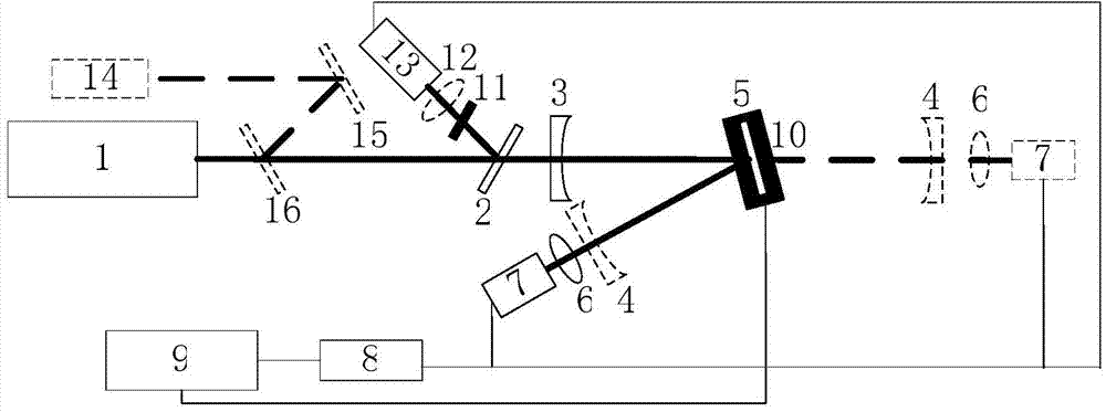
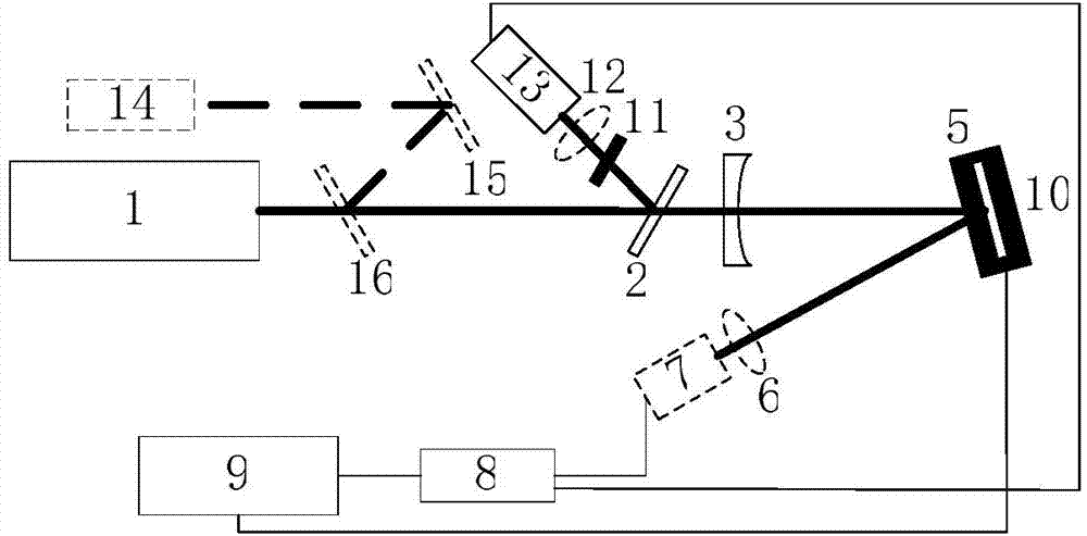
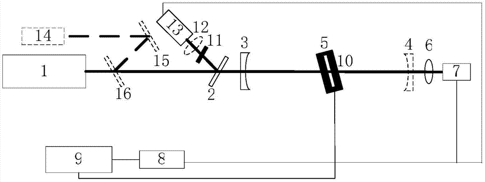
[0025] Combine below Figure 1 to Figure 3 The measurement system describes a comprehensive measurement method of reflectivity based on a pulsed laser light source of the present invention.

[0026] The light source 1 is a pulsed laser, the laser output pulse line width is greater than the free spectral range of the resonator; the pulsed laser beam is split into a reference beam and a detection beam by the plane high reflector 2, and the reference beam is attenuated by the variable attenuator 11 and then passed by the focusing lens 12 Focus on the photodetector 13, adjust the variable attenuator 11 to make the light intensity of the reference beam equal to the light intensity of the detection beam; the output signals of the photodetectors 7 and 13 are collected by the data acquisition card 8 and input to the computer 9 for storage and processing; visible auxiliary The light source 14, reflector 15 and beam splitter 16 are used to assist in adjusting the optical path. If the li...


PUM


Abstract

The invention relates to a reflectivity and transmittance comprehensive measurement method based on a pulse laser light source. The method includes the steps that a pulse laser light beam is split into a reference light beam and a detection light beam, the reference light beam is focused on a photoelectric detector for direct detection, and the detection light beam is injected into an optical resonance cavity. When an optical element with reflectivity larger than 99% is measured, a pulsed light cavity ring-down technology is adopted, ring-down time tau 0 of an output signal of the initial optical resonance cavity and ring-down time tau 1 of an output signal of the optical resonance cavity after the optical element to be detected is installed in the optical resonance cavity are measured, and reflectivity R of the optical element to be detected is obtained through calculation. When the value of R is smaller than 99%, a spectrophotometry is used for measuring the reflectivity of the optical element to be detected. An output cavity lens of the optical resonance cavity is moved away, detection light reflected from the optical element to be detected is focused on the photoelectric detector for detection, the light intensity signal ratio of the detection light beam and the reference light beam is recorded, and the reflectivity R of the optical element to be detected is obtained through calibration.

Description

technical field [0001] The invention relates to the technical field for measuring the reflectivity of reflective optical elements and the transmittance of transmissive optical elements, in particular to a method for measuring the reflectivity and transmittance of arbitrary reflectivity optical elements and large-diameter optical elements based on a pulsed laser light source . Background technique [0002] Spectrophotometry is the most common method for measuring the transmission and reflection of optical components. In principle, as long as the reflected light energy flow E is measured r and the incident light can stay E 1 , the reflectivity is E r / E 1 . In actual measurement, the fluctuation of the output power of the laser light source is an important factor affecting the measurement results. For some high-reflectivity optical components with a reflectivity of over 99.9%, the light intensity is very close between the optical component without the optical component t...

Claims


Application Information

Patent Timeline
Patent Type & Authority Applications(China)
IPC IPC(8): G01M11/02
Inventor 李斌成祖鸿宇韩艳玲
Owner INST OF OPTICS & ELECTRONICS - CHINESE ACAD OF SCI
Why Eureka
Try Eureka