Gas chemical solvent absorption and desorption reaction heat measuring device and measuring method

A chemical solvent, measuring device technology, applied in the direction of measuring devices, scientific instruments, material thermal development, etc., can solve the problems of heat measurement error, error, heat conduction loss, etc., to achieve the effect of easy calculation

Inactive Publication Date: 2014-03-05
SINOPEC PETROLEUM ENG DESIGN +3
View PDF5 Cites 18 Cited by
  • Summary
  • Abstract
  • Description
  • Claims
  • Application Information

AI Technical Summary

Problems solved by technology

However, the analysis shows that when the electric heater outside the reactor heats up the sample in the reactor in this method, the temperature of the heater area rises higher than the temperature of the sample in the reactor, which is higher than the temperature of the outer protective shell, causing part of the heat to be conducted to the periphery Dissipation, which will cause large errors when measuring heat
In addition, when the invention is applied to a large-volume reactor, if an exothermic reaction occurs in the reactor, a large amount of heat is generated to cause uneven temperature distribution of the solvent sample, and the wall temperature of the reactor is lower than the central temperature of the sample. The method of still controlling the minimum temperature difference between the metal wall of the outer protective shell and the center of the sample will cause the heat to be conducted to the reactor, which will bring errors to the heat measurement

Method used


Image

  • Gas chemical solvent absorption and desorption reaction heat measuring device and measuring method
  • Gas chemical solvent absorption and desorption reaction heat measuring device and measuring method
  • Gas chemical solvent absorption and desorption reaction heat measuring device and measuring method

Examples


Embodiment Construction

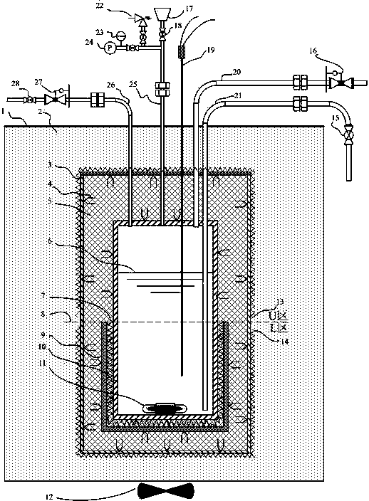
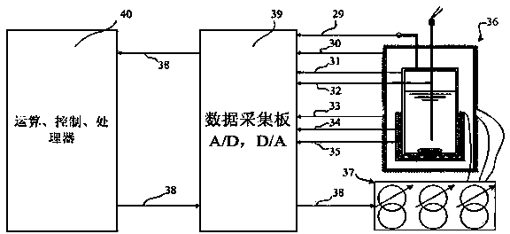
[0024] see figure 1 and figure 2 Shown: the reaction calorimeter of the present invention, which is composed of: the metal inner shell (3) and the outer shell (1) are filled with heat insulating material (2) in the middle. The dotted line separating the regions (8) will figure 1 It is divided into two areas, U and L, representing the upper and lower areas respectively. The electric heater H is distributed in the outer U area of ​​the inner shell (3) GU (13), the electric heater H is distributed in the outer L area GL (14), multiple sets of temperature measuring thermocouples (4) are evenly distributed on the inner side, and the average temperatures of the measured U and L regions are T GU (30) and T GL (33). The gap between the inner shell (3) and the reactor (10) is filled with glass fiber insulation material (5), and the main electric heater H is distributed in the area L outside the reactor (10) R (7), and its outer side is covered with a certain thickness of glass ...


PUM


Abstract

Provided is a gas chemical solvent absorption and desorption reaction heat measuring device. The measuring device comprises an outer shell, an inner shell, a pressure sensor, a data collecting plate, a computer and a power supply. A reactor is arranged in the central part of the inner shell. Heat insulation materials are arranged between the outer shell and the inner shell. Thermal resistance heater HGU and HGL are arranged at the upper part and the lower part of the periphery of the inner shell respectively. Glass fiber heat insulation layers are arranged between the inner shell and the reactor. Thermocouples are arranged in the heat insulation layers. A glass fiber plate is arranged at the periphery of the middle and lower part of the reactor. A thermal resistance main heater HR is arranged between the glass fiber plate and the reactor. A liquid inlet pipe and a gas discharging pipe at the upper part the reactor to the upper and top part of the outer shell. Thermocouples and a liquid discharging pipe are arranged at the bottom and upper part to the top and upper part of the outer shell. The signal wires of the pressure sensor, the thermocouples inside the inner shell, the thermocouples inside the reactor, the thermocouples outside the reactor and the glass fiber plate thermocouples are connected with the data collecting plate. The data collecting plate is connected with the computer. The power supply is connected with the electric heaters outside the inner shell and the reactor.

Description

technical field [0001] The present invention relates to a CO 2 、H 2 S or SO 2 The gas chemical solvent absorption and desorption reaction heat measurement device and measurement method use the precise control of the electric heater to realize the adiabatic environment of the reaction system so as to accurately measure the exothermic heat of the absorption reaction process and the endothermic heat of the desorption reaction process. Background technique [0002] In the current natural gas acid gas purification, coal-fired power plant flue gas CO 2 In industries such as capture, the chemical solvent absorption method is a method that is easy to realize large-scale industrial applications and has broad prospects. However, the regeneration process after chemical solvent absorption requires a lot of heat energy, resulting in high operating costs, so the energy consumption characteristics of various chemical solvent formulations determine their economic feasibility. Therefore,...

Claims


Application Information

Patent Timeline
Patent Type & Authority Applications(China)
IPC IPC(8): G01N25/48
CPCG01N25/4826
Inventor 张建李清方刘海丽陆诗建尚明华王鑫何利民黄少伟张新军孙广领单童王增林庞会中刘东杰于惠娟孙志英吴鲁宁朱红彬张宁宁张磊陆胤君
Owner SINOPEC PETROLEUM ENG DESIGN
Why Eureka
Try Eureka