Laser scanning confocal microscope imaging system

A technology of confocal microscope and imaging system, applied in the field of optical detection of microscope objective lens, can solve the problems of affecting image quality, fluorescence bleaching, long time, etc., and achieve the effect of improving image imaging quality and fast scanning speed

Active Publication Date: 2014-03-05
SUZHOU INST OF BIOMEDICAL ENG & TECH CHINESE ACADEMY OF SCI
View PDF5 Cites 22 Cited by
  • Summary
  • Abstract
  • Description
  • Claims
  • Application Information

AI Technical Summary

Problems solved by technology

This process requires multiple scans of the sample with a strong laser, which is prone to fluore...

Method used


Image

  • Laser scanning confocal microscope imaging system
  • Laser scanning confocal microscope imaging system
  • Laser scanning confocal microscope imaging system

Examples


Embodiment Construction

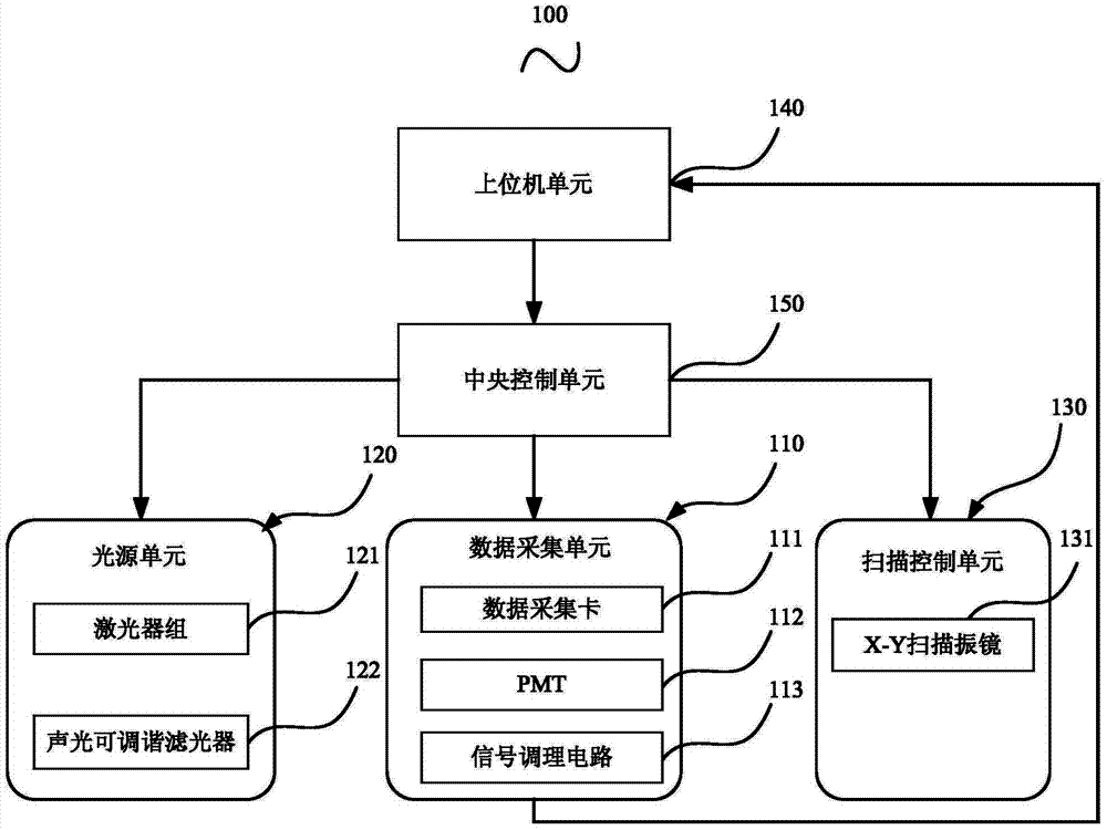
[0025] Please refer to figure 1 , figure 1 A schematic structural diagram 100 of a laser scanning confocal microscope imaging system provided by an embodiment of the present invention.

[0026] The laser scanning confocal microscope imaging system 100 includes a data acquisition unit 110 , a light source unit 120 , a scanning control unit 130 , a host computer unit 140 and a central control unit 150 .

[0027] Wherein, the data acquisition unit 110 is electrically connected to the upper computer unit 140, the upper computer unit 140 is electrically connected to the central control unit 150, and the central control unit 150 is electrically connected to the data acquisition unit 110, the light source unit 120 and the scanning control unit 130 .

[0028] The data acquisition unit 110 pre-scans the sample to be tested and obtains the fluorescence intensity data, the host computer unit 140 collects the fluorescence intensity data and calculates the scanning parameters of the imag...


PUM


Abstract

The invention provides a laser scanning confocal microscope imaging system which comprises a data collecting unit, a light source unit, a scanning control unit, an upper computer unit and a central control unit. By means of the upper computer unit, fluorescence intensity data are collected and scanning parameter of the imaging system are calculated according to the fluorescence intensity data, the central control unit generates a control signal of the data collecting unit, the light source unit and the scanning control unit according to the scanning parameters sent by the upper computer unit, and scanning and imaging of a sample to be detected are achieved. Accordingly, a scanned image with a satisfying signal-to-noise ratio is obtained, and imaging quality is improved.

Description

technical field [0001] The invention relates to the technical field of optical detection of a microscope objective lens, in particular to a laser scanning confocal microscope imaging system. Background technique [0002] Laser Scanning Confocal Microscopy (LSCM) is an effective technical means for studying submicron microstructures, and it is a necessary large-scale scientific research instrument for scientific and technological workers engaged in biomedical and material science research at home and abroad. In LSCM, a photomultiplier tube (Photomultiplier Tube, PMT) is used as a fluorescence detector to collect weak fluorescence signals, which has the advantages of high resolution and high sensitivity. Under the extremely weak light signal, the PMT output signal presents the output characteristic of pulse signal; under the weak light signal, the PMT output signal presents the output characteristic of superposition of pulse signal and DC signal. [0003] For the LSCM system,...

Claims


Application Information

Patent Timeline
IPC IPC(8): G02B21/00G02B21/06G02B21/36G01N21/64
Inventor 黄维张运海高飞薛晓君
Owner SUZHOU INST OF BIOMEDICAL ENG & TECH CHINESE ACADEMY OF SCI
Why Eureka
Try Eureka