Check patentability & draft patents in minutes with Patsnap Eureka AI!

High-power high-frequency power supply system for high-potential electronic circuit and method of high-power high-frequency power supply system

A high-frequency power supply and electronic circuit technology, applied in the field of electronics, can solve problems such as difficulty in applying to 35kV voltage and above, poor overall performance consistency of the power supply system, unfavorable product modularization and standardization, etc., to optimize energy transmission efficiency, reduce Dispersion, low harmonic effect

Inactive Publication Date: 2014-03-05
STATE GRID CORP OF CHINA +1
View PDF5 Cites 1 Cited by
  • Summary
  • Abstract
  • Description
  • Claims
  • Application Information

AI Technical Summary

Problems solved by technology

[0007] 1) The high-voltage insulation problem between the ground power supply part of the high-frequency energy transmission system and the high-potential electronic circuit;
[0008] 2) Consistency of distribution parameters;
[0009] 3) The problem of load adaptability;
[0010] 4) The overall efficiency of the high-frequency power supply system
[0011] The current source method proposed in the patent CN101222183A only relies on the insulation of the cable itself to solve the insulation problem of the energy transmission power supply system, which is difficult to apply to 35kV voltage and above, and has the problem of poor consistency of distributed parameters
The voltage source method proposed in the patent CN201904717U uses the insulation of cables and transformers to solve the insulation problem of the energy transmission power supply system. It can be applied to 35kV voltage and above. However, due to uncertain factors in the layout and fixing of cables, its distribution parameters Difficult to control, making the overall performance of the power system less consistent
In addition, in the high-frequency energy transmission scheme proposed by the patent CN201904717U, the primary sides of all the current transformer monomers that provide energy to the trigger electronic circuit are connected in series. The number of series connection is different, and the parameters of the designed high-frequency transformer are also different. , which is not conducive to the modularization and standardization of products

Method used


Image

  • High-power high-frequency power supply system for high-potential electronic circuit and method of high-power high-frequency power supply system
  • High-power high-frequency power supply system for high-potential electronic circuit and method of high-power high-frequency power supply system

Examples


Embodiment 1

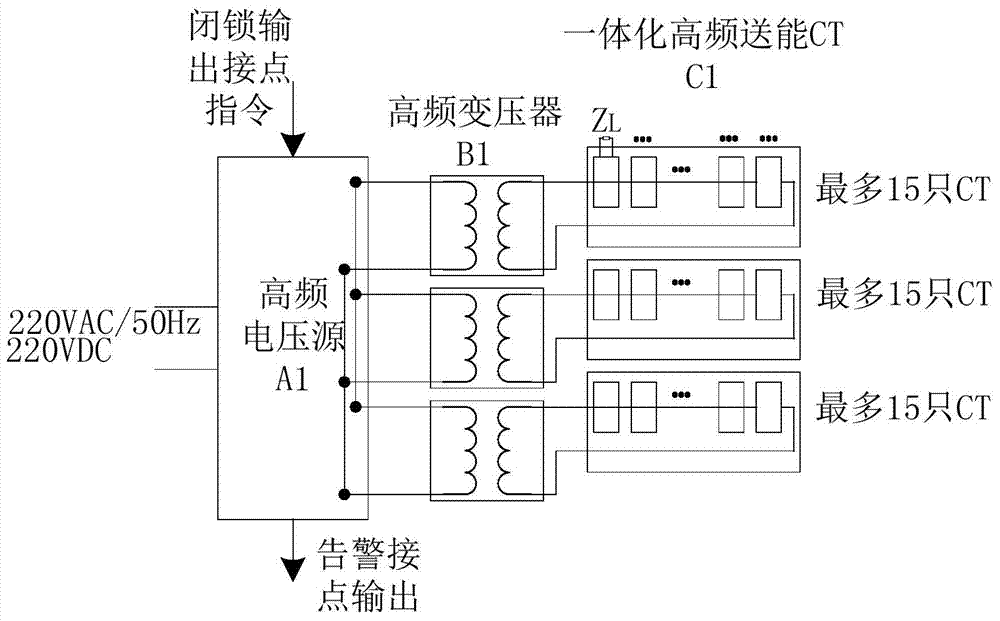
[0053] Such as figure 1 As shown, this embodiment includes: one high-frequency voltage source A1, three high-frequency transformers B1 and three-column casting integrated high-frequency energy-transmitting CT C1. Among them: the input end of the high-frequency voltage source A1 is connected to low-voltage DC voltage or AC mains, and the input voltage is converted into a high-frequency signal, which is output to three high-frequency transformers B1; the primary sides of the three high-frequency transformers B1 are connected in parallel, Connect to the output of the high-frequency power supply, and each of the secondary sides is connected to a cast-type integrated high-frequency energy-transmitting CT C1; the high-frequency energy-transmitting CT is connected in series by the primary sides of up to fifteen high-frequency CT monomers and then connected to a high-frequency transformer The secondary side is connected to the valve body at a single point equipotentially, and the seco...

Embodiment 2

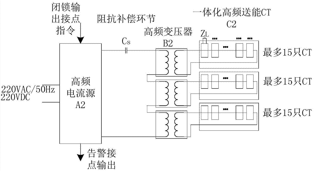
[0058] Such as figure 2 As shown, this embodiment includes: one high-frequency current source A2, three high-frequency transformers B2, three-column casting integrated high-frequency energy-transmitting CT C2 and impedance compensation link Cs. Among them: the input end of the high-frequency current source A2 is connected to a low-voltage DC voltage or AC mains, and the input voltage is converted into a high-frequency signal. After the primary sides of the three high-frequency transformers B2 are connected in series, one end is connected to the impedance compensation link Cs, One end is connected to an output end of the high-frequency current source A2; the other end of the impedance compensation link Cs is connected to the other output end of the high-frequency voltage source A2. The secondary sides of the three high-frequency transformers B2 are each connected to a cast-type integrated high-frequency energy-transmitting CT C1; the high-frequency energy-transmitting CT is co...


PUM


Abstract

The invention relates to a high-power high-frequency power supply system for a high-potential electronic circuit and a method of the high-power high-frequency power supply system. The system comprises a high-frequency power supply, a high-frequency high-voltage transformer, a poured integrated high-frequency energy transmission CT (current transformer) and an impendence compensation link which are connected with one another in sequence, wherein the high-frequency power supply comprises a high-frequency current source and a high-frequency voltage source. The method comprises the steps of (1) connecting the high-frequency power supply to low-voltage direct current voltage or alternating current mains supply; and (2) converting the connected voltage into a high-frequency signal, and outputting the high-frequency signal to the high-frequency transformer. According to the system and the method which are disclosed by the invention, the dispersibility of distribution parameters is reduced, and electrical isolation of all trigger electronic circuits is realized; due to the high-frequency transformer, insulation between a low-potential part and a high-potential part of an energy transmission power supply system is realized; the energy transmission efficiency is optimized. The system and the method meet requirements on modularization and standardization of a product, are high in load adaptability and also meet a requirement on energy for continuously triggering a thyristor valve.

Description

technical field [0001] The invention belongs to electronic technology, and specifically relates to a high-potential electronic circuit high-power high-frequency power supply system and a method thereof. Background technique [0002] Compared with traditional adjustment methods, power electronic technology has obvious advantages in the flexible adjustment of electric energy, and it has been widely used in power systems. Thyristor valves and other power electronic devices are used as power changing parts, and the voltage level of their applications is getting higher and higher. The high-potential electronic circuits triggered by them are generally installed on the valve body and are at high potential to provide stable and reliable power. Supply is one of the key links to improve the overall stability of power electronic devices. [0003] There are two modes of power supply for high-potential electronic circuits: energy acquisition and energy delivery. The energy harvesting m...

Claims


Application Information

Patent Timeline
Patent Type & Authority Applications(China)
IPC IPC(8): H02M1/00
Inventor 詹雄赵刚袁洪亮赵波郭文明任西周吴韬
Owner STATE GRID CORP OF CHINA
Features
  • R&D
  • Intellectual Property
  • Life Sciences
  • Materials
  • Tech Scout
  • Unparalleled Data Quality
  • Higher Quality Content
  • 60% Fewer Hallucinations
Learn More