Solar cell piece PID (potential induced degradation) test device and test method

A technology for solar cells and testing devices, which is applied in the monitoring of photovoltaic power generation, electrical components, photovoltaic systems, etc., can solve the problems of long test cycle, complex process, and the inability to timely feedback the quality of battery production process anti-PID, and achieve The effect of saving test time, saving inspection cost and optimizing production process

Active Publication Date: 2014-03-05
ZHEJIANG JINKO SOLAR CO LTD +1
View PDF4 Cites 11 Cited by
  • Summary
  • Abstract
  • Description
  • Claims
  • Application Information

AI Technical Summary

Problems solved by technology

Since the component manufacturing process and packaging materials also have a great influence on the PID effect of the component, the PID test result of the component cannot directly reflect whether the cell is res

Method used


Image

  • Solar cell piece PID (potential induced degradation) test device and test method
  • Solar cell piece PID (potential induced degradation) test device and test method

Examples


Embodiment 1

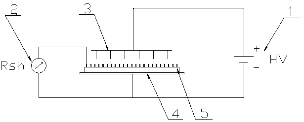
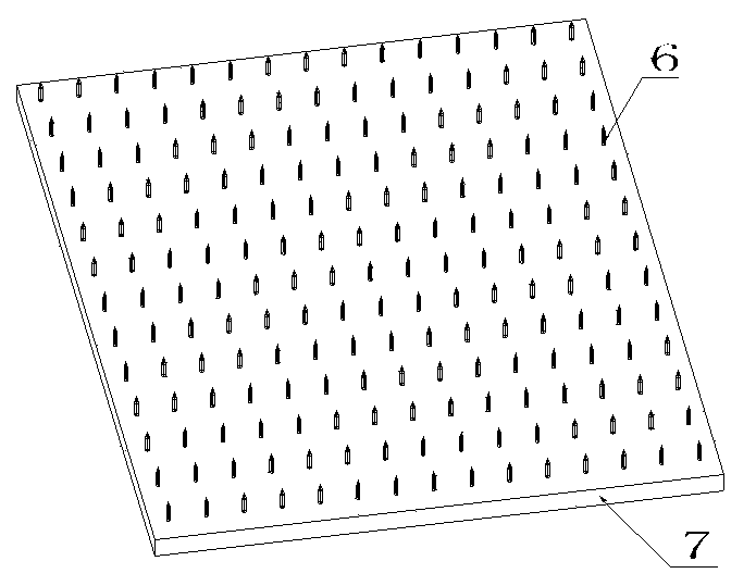
[0025] Embodiment 1: as figure 1 Shown is a solar cell PID test device, which is used for testing 5-inch and 6-inch solar cells, including a DC voltage device 1, a resistance tester 2, a metal electrode row 3 and a metal tray 4, and the metal electrode row 3 and the The positive pole of the DC voltage generator 1 is connected, the metal tray 4 is connected with the negative pole of the DC voltage generator 1, one of the test lines of the resistance tester 2 is connected with the metal tray 4, and the other test line is used to connect the electrodes of the solar battery sheet 5 . The metal electrode row 3 is composed of 225 metal electrodes 6 welded on a metal plate 7 of 160mm×160mm, such as figure 2 . The distance between the metal electrode row 3 and the metal tray 4 can be adjusted so that when the solar cell 5 is placed on the metal tray 4 during testing, the distance between the metal electrode row 3 and the electrodes of the solar cell 5 is 0.1-10 cm. The DC voltage ...

Embodiment 2

[0026] Embodiment 2: A solar cell PID test method, using the solar cell PID test device provided in Example 1, the specific test steps are as follows:

[0027] (1) Place the solar cells 5 on the metal tray 4, and control the distance between the metal electrodes 6 of the metal electrode row 3 and the electrodes of the solar cells 5 to be 2 cm. Connect the test line of the resistance tester 2, control the ambient temperature to 25°C, and the relative humidity to 80%;

[0028] (2) Turn on the DC voltage device 1, and cause the metal electrode row 3 to generate corona discharge under the action of a high voltage of 20KV, and the ion flow acts on the surface of the solar cell 5;

[0029] (3) Continuously irradiate the solar cells 5 with ions for 6 hours, and take samples once / 20 minutes (test every 20 minutes) to test the changes in the parallel resistance of the solar cells 5 in real time;

[0030] ⑷ Make a graph to record the change of parallel resistance.

[0031] Analyze the...


PUM


Abstract

The invention relates to a solar cell piece potential induced degradation (PID) test device and a test method. The test device comprises a direct current voltage device, a resistance tester, a metal electrode array and a metal tray. The test method comprises the following steps: (1). a cell piece is placed on the metal tray, a temperature is controlled to be 0 to 100 DEG C and humidity to be 0 to 100%; (2). the direct current voltage device opens so that an ion flow is applied to a surface of the solar cell piece; (3) ion radiation continues and cell piece parallel resistance changes are tested in a real-time manner; and (4) a curve chart is made for recording the parallel resistance changes. In the invention, the parallel resistance of the solar cell piece is tested directly, and the anti PID effect is determined, i.e. the anti PID effect test at the solar cell terminal is conducted, so that the test cost and test time are saved; the timely optimization of the anti PID cell production process is facilitated; and an effective monitoring is realized at the same time.

Description

technical field [0001] The invention belongs to the field of crystalline silicon solar cell manufacturing, and in particular relates to a solar cell potential-induced decay (PID) testing device and testing method. Background technique [0002] The PID (Potential Induced Degradation) effect is called the high-voltage induced attenuation effect, and it is a relatively new attenuation effect that has appeared in the photovoltaic field in recent years. [0003] With the gradual promotion and application of photovoltaic grid-connected systems, the system voltage is getting higher and higher, commonly used are 600V and 1000V. The pressure of the cells inside the module relative to the ground is getting higher and higher, and some even reach 600-1000V. Generally, the aluminum frame of the module is required to be grounded, so that a high voltage of 600-1000V is formed between the battery sheet and the aluminum frame. Generally speaking, during the lamination process of component ...

Claims


Application Information

Patent Timeline
IPC IPC(8): H02S50/10
CPCY02E10/50
Inventor 刘长明陈康平金浩黄琳
Owner ZHEJIANG JINKO SOLAR CO LTD
Why Eureka
Try Eureka