Polishing head and polishing apparatus
A technology of grinding head and rigid ring, which is applied in the field of grinding head, can solve the problems of poor flatness of workpiece and uneven thickness of backing film, etc.
- Summary
- Abstract
- Description
- Claims
- Application Information
AI Technical Summary
Problems solved by technology
Method used
Image

Examples
Embodiment 1~ Embodiment 3
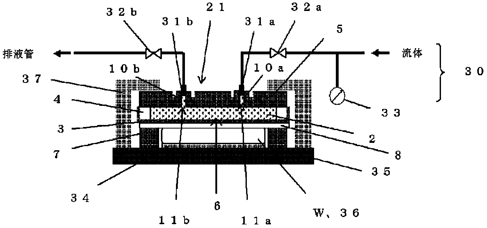
[0099] Use as image 3 In the polishing apparatus of the present invention shown as the polishing head of the present invention, the workpiece was polished, and the variation in the grinding allowance in the surface of the polished workpiece was evaluated. As the workpiece W, a silicon single crystal wafer having a diameter of 300 mm and a thickness of 775 μm was used. Here, the thickness of the wafer before and after polishing is measured using a flatness measuring device as a flatness guaranteed region except for the 2 mm width of the outermost peripheral portion, and the difference between the thicknesses before and after polishing in the diameter direction cross section of the wafer is calculated to calculate Grinding allowance. As a flatness measuring device, a flatness measuring device (Wafer Sight) manufactured by KLA-Tencor was used.
[0100] First, the following polishing head was prepared. A rigid ring made of SUS with an outer diameter of 360 mm and an inner diam...
Embodiment 4~ Embodiment 7
[0111] Silicone rubber was pasted under the conditions of tension of 5N (Example 4), 20N (Example 5), 35N (Example 6), and 48N (Example 7). Conditions A silicon single crystal wafer was polished, and in the same manner as in Example 1, variations in the polishing allowance in the polished wafer surface were evaluated.
[0112] The distribution of the polishing allowance of the wafers polished in Examples 4 to 7 is shown in FIG. 7(A). In addition, as the grinding allowance distribution of the outer peripheral part of a wafer, the grinding allowance distribution in the range of 120 mm - 148 mm from a wafer center is shown in FIG. 7(B). As shown in FIG. 7(A) and FIG. 7(B), it can be seen that in any of the cases of Examples 4 to 7, it is possible to uniformly polish to the outer peripheral portion of the wafer.
[0113] In addition, as an index showing the distribution of the grinding allowance at the outer peripheral portion of the wafer, the difference between the maximum valu...
Embodiment 8、 Embodiment 9
[0116] In order to investigate the influence of the filling pressure of the incompressible fluid, the pressure at the time of filling was set to 10kPa (Example 8) and 40kPa (Example 9) and the polishing head filled with pure water was used. In addition, a silicon single crystal wafer was polished under the same conditions as in Example 7, and the variation in the polishing allowance in the wafer surface after polishing was evaluated in the same manner as in Example 7.
[0117] exist Figure 9, represents the distribution of the grinding allowance in the peripheral portion of the wafer polished in Example 8 and Example 9. As mentioned above, the deviation of the polishing allowance at the outer peripheral portion of the wafer in Example 7 was 0.011 μm. On the other hand, when the filling pressure is 10 kPa lower than the pure water filling pressure of 20 kPa in Example 7, that is, Example 8 In the case of , the deviation of the grinding margin at the outer peripheral portion o...
PUM
 Abstract
Description
Claims
Application Information
 - R&D
- Intellectual Property
- Life Sciences
- Materials
- Tech Scout
- Unparalleled Data Quality
- Higher Quality Content
- 60% Fewer Hallucinations
Browse by: Latest US Patents, China's latest patents, Technical Efficacy Thesaurus, Application Domain, Technology Topic, Popular Technical Reports.
© 2025 PatSnap. All rights reserved.Legal|Privacy policy|Modern Slavery Act Transparency Statement|Sitemap|About US| Contact US: help@patsnap.com