Aeration system capable of being cleaned on line
An aeration system and gas pipeline technology, which is applied in the field of aeration systems, can solve the problems that the diaphragm aerator cannot be cleaned online, and achieve the effects of maintaining high-efficiency operation, saving energy and reducing consumption, and improving aeration effect
- Summary
- Abstract
- Description
- Claims
- Application Information
AI Technical Summary
Problems solved by technology
Method used
Image
Examples
Embodiment 1
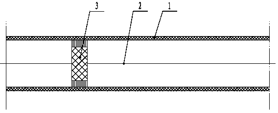
[0027] Such as figure 1 As shown, it includes a diaphragm 1 provided with self-closing micropores, the diaphragm 1 is tubular, and a stay cord 2 that can reciprocate left and right is arranged in the tubular diaphragm 1, and a stay cord 2 is fixedly installed on the stay cord 2. A brush 3 for cleaning the diaphragm 1. The diaphragm 1 is designed in a tubular shape, and a brush 3 that can reciprocate with the pull cord 2 is installed inside it, which can realize online cleaning of the interior, prevent self-closing micropores from being blocked, improve aeration effect, and reduce energy consumption , Prolong the service life of the diaphragm 1.
Embodiment 2
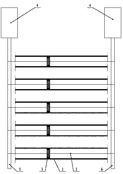
[0029] Such as figure 2 As shown, it includes a plurality of tubular diaphragms 1 arranged side by side. The tubular diaphragms 1 are all provided with pull cords 2 that can reciprocate left and right. Brush 3; left shaft 5 and right shaft 6 connected with power equipment 4 are arranged at both ends of a plurality of tubular diaphragms 1 arranged side by side, and the two ends of the stay rope 2 are wound around the left shaft 5 and the right shaft respectively. on axis 6. Through the arrangement of the left shaft 5 and the right shaft 6, simultaneous cleaning of multiple tubular diaphragms 1 arranged side by side can be realized.
Embodiment 3
[0031] Such as image 3 As shown, the difference from Embodiment 2 is that both ends of the tubular diaphragm 1 are respectively fixedly connected to the left main pipe 7 and the right main pipe 8 with both ends closed, and the left shaft 5 and the right shaft 6 are respectively It is arranged in the left supervisor 7 and the right supervisor 8. Air is supplied to multiple tubular diaphragms 1 arranged side by side through the left main pipe 7 and the right main pipe 8 . The left shaft 5 and the right shaft 6 are arranged inside the left main pipe 7 and the right main pipe 8, the structure is ingenious and simple, and the contact and corrosion of the left shaft 5 and the right shaft 6 with sewage are avoided at the same time.
[0032] Another example Figure 4 As shown, the left main pipe 7 is connected with a gas pipeline 9, and the gas pipeline 9 is connected with a blower 10 and a valve 11; the blower 10 is connected with a frequency conversion controller 12; the gas pipe...
PUM
 Abstract
Description
Claims
Application Information
 - R&D
- Intellectual Property
- Life Sciences
- Materials
- Tech Scout
- Unparalleled Data Quality
- Higher Quality Content
- 60% Fewer Hallucinations
Browse by: Latest US Patents, China's latest patents, Technical Efficacy Thesaurus, Application Domain, Technology Topic, Popular Technical Reports.
© 2025 PatSnap. All rights reserved.Legal|Privacy policy|Modern Slavery Act Transparency Statement|Sitemap|About US| Contact US: help@patsnap.com


