Small-sized and multipurpose high-pressure pump

A high-pressure pump, multi-purpose technology, applied in the direction of components, pumps, pump components, etc. of pumping devices for elastic fluids, can solve the problem of unreasonable structural design of discharge valve and liquid inlet valve, and no space for forced cooling system , lubricating oil lubricating performance decline and other problems, to achieve the effect of improving heat dissipation, simple structure, thinner wall thickness

Inactive Publication Date: 2014-03-12
TIANJIN TONGJIE HIGH PRESSURE PUMP
View PDF6 Cites 4 Cited by
  • Summary
  • Abstract
  • Description
  • Claims
  • Application Information

AI Technical Summary

Problems solved by technology

[0003] 1. The box on the power end is made of HT250 cast iron or QT600 ductile iron, and the rear cover is made of cast aluminum for heat dissipation. Since there is no heat dissipation on the surface of the box, the temperature inside the box may be as high as 60 degrees or more during use, resulting in The lubricating properties of the lubricating oil are reduced, resulting in increased wear of the components, thus shortening the service life of the product
[0004] 2. Since the volume of the high-pressure pump for this vehicle cannot be too large, there is basically no space for adding a forced cooling system
[0005] 3. Since the liquid discharge valve and the liquid inlet valve are respectively installed in the upper and lower parts of the upper cavity of the pump head, and the liquid discharge valve and the liquid inlet valve are both split plate valve structures, a suppo

Method used


Image

  • Small-sized and multipurpose high-pressure pump
  • Small-sized and multipurpose high-pressure pump
  • Small-sized and multipurpose high-pressure pump

Examples


Example Embodiment

[0027] The small-sized, multi-purpose high-pressure pump provided by the present invention will be described in detail below with reference to the drawings and specific embodiments.

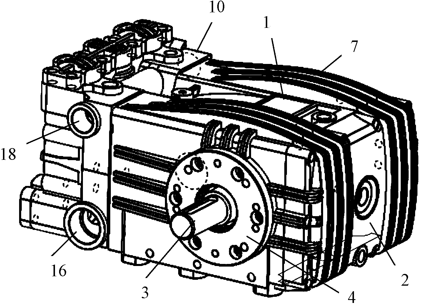
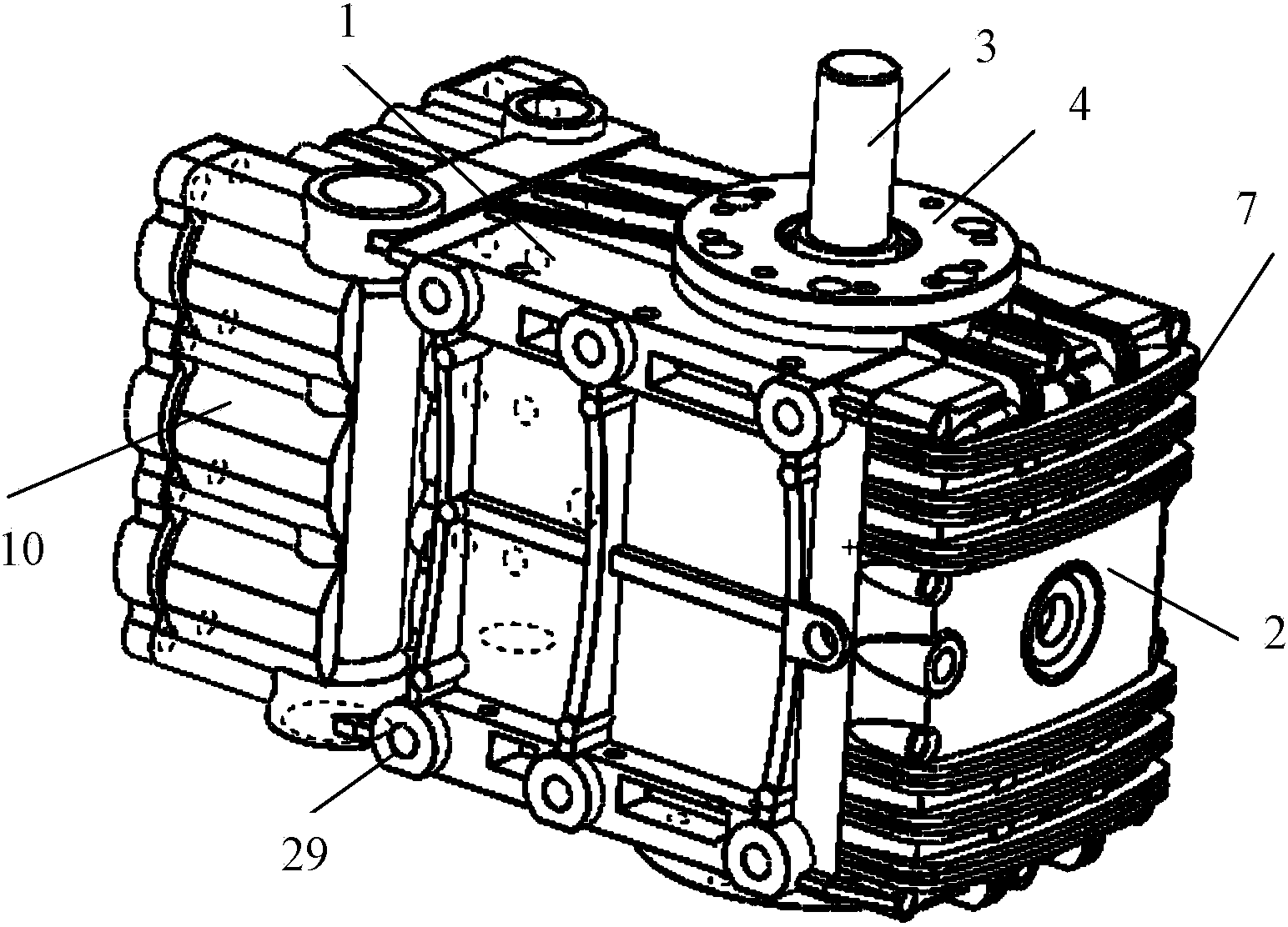
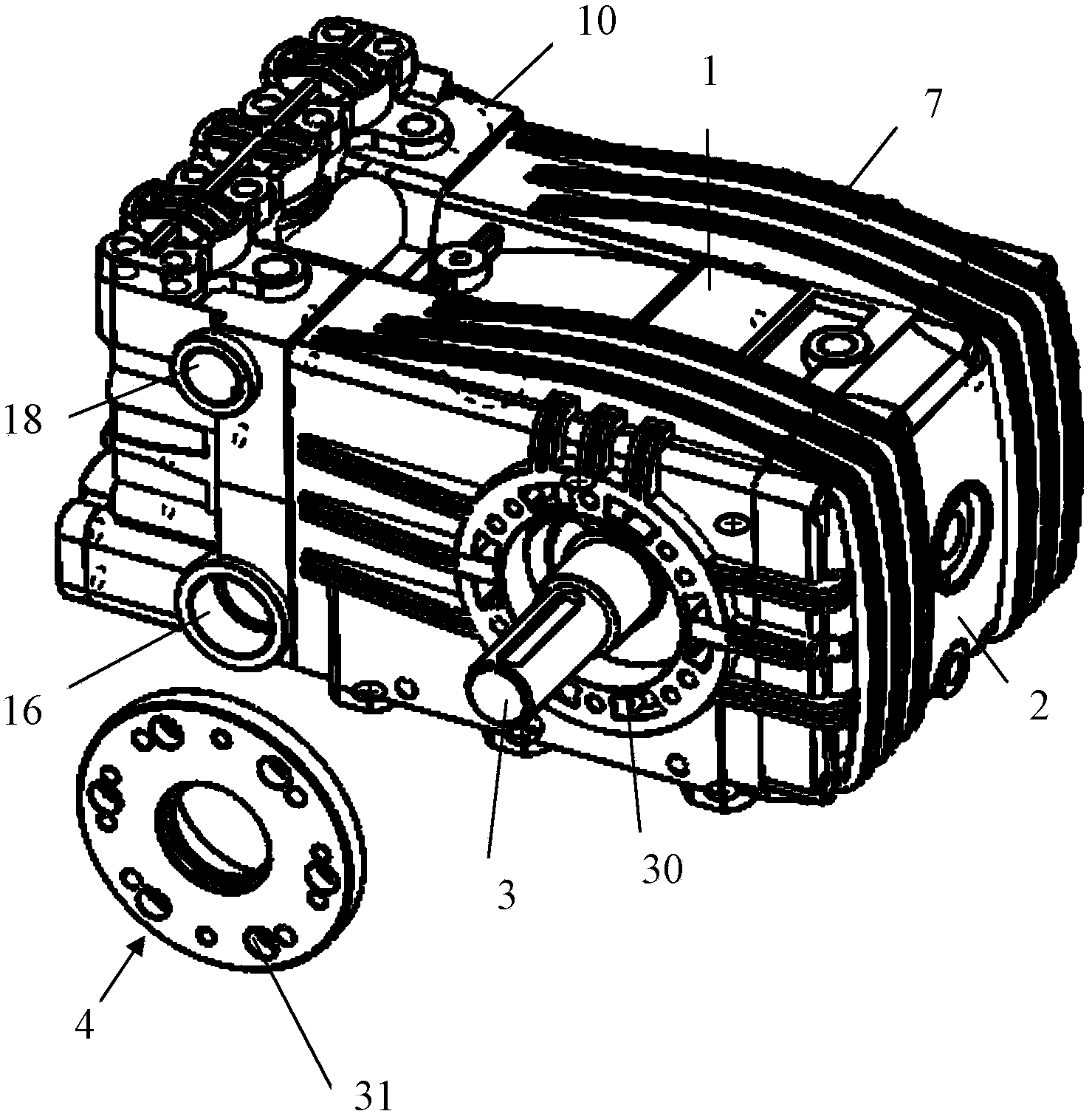
[0028] Such as figure 1 — Picture 9 As shown, the small, multi-purpose high-pressure pump provided by the present invention is composed of a power end and a hydraulic end. The power end includes a crankcase 1, a rear cover 2, a crankshaft 3, a crankshaft end cover 4, and multiple connecting rods. 5 and an integrated intermediate rod 6; the bottom surface of the crankcase 1 is recessed inward, and the rear end is formed with an opening; the rear cover 2 covers the rear opening of the crankcase 1, and the crankcase 1 and the rear cover 2 are formed with multiple A radiating fin 7; the crankshaft 3 is horizontally arranged inside the crankcase 1, one end penetrates the side wall of the crankcase 1 and extends to the outside, and this end is connected to the drive motor, and a plurality of eccentric pa...


PUM


Abstract

The invention relates to a small-sized and multipurpose high-pressure pump. The small-sized and multipurpose high-pressure pump is composed of a power end and a hydraulic end, wherein the power end comprises a crank case, a back cover, a crankshaft, a crankshaft end cover, a plurality of connecting rods and an integrated intermediate rod; the hydraulic end comprises a pump head, a plurality of intake valves and a plurality of drain valves. The small-sized and multipurpose high-pressure pump has the following advantages: because the original crosshead and plunger rod are replaced by the integrated intermediate rod, the coaxiality is good, assembly is convenient, and meanwhile, the size of the product can be reduced; the crank case and the back cover are provided with fins, the crankshaft end cover is provided with heat-dissipating holes, meanwhile, the part of the crank case, which corresponds to the heat-dissipating holes, is provided with slots, moreover, the middle of the bottom of the crank case is sunken upwardly, consequently, the coercive measures can ensure that the heat in the crank case can be dissipated out as soon as possible, so that the lubricating property of the lubricating oil in the crank case cannot be affected, as a result, the parts in the crank case can be prevented from being abraded, and thereby the service life of the entire product can be prolonged. The arrangement of the fins also can play a reinforcing role at the same time.

Description

Technical field [0001] The invention belongs to the technical field of hydraulic machinery, and particularly relates to a small-sized, multi-purpose high-pressure pump. Background technique [0002] The high-pressure pump, also known as the plunger pump, is an important device of the hydraulic system. It is mainly composed of a power end and a hydraulic end. The power end is used to transfer the energy of the prime mover to the hydraulic end, and the hydraulic end is used to convert mechanical energy. It is liquid pressure energy, and its working principle is to rely on the reciprocating movement of the plunger in the cylinder to change the volume of the sealed working chamber to achieve suction and compression of the medium. It has high rated pressure, compact structure, high efficiency and convenient flow adjustment. Advantages, it is widely used in high pressure, large flow and occasions where flow needs to be adjusted, such as hydraulic presses, engineering machinery, oil fie...

Claims


Application Information

Patent Timeline
IPC IPC(8): F04B17/03F04B53/00F04B53/08F04B53/10
Inventor 李福兴李金朱金牛
Owner TIANJIN TONGJIE HIGH PRESSURE PUMP
Why Eureka
Try Eureka