Non-refrigeration infrared imaging focal plane array detector

A focal plane array, uncooled infrared technology, applied in the direction of instruments, measuring devices, scientific instruments, etc., can solve the problems of reducing the sensitivity of the detector, low utilization rate of graphics, and difficulty in further reducing the resolution of the pixel area, so as to reduce thermal crosstalk , Reduce process complexity, reduce the effect of impact

Inactive Publication Date: 2014-03-12
INST OF MICROELECTRONICS CHINESE ACAD OF SCI
View PDF5 Cites 4 Cited by
  • Summary
  • Abstract
  • Description
  • Claims
  • Application Information

AI Technical Summary

Problems solved by technology

The former needs to keep the silicon substrate, so when the infrared rays pass through the silicon substrate, 40% of the infrared light will be lost due to reflection, which will reduce the sensitivity of the detector; although the latter has no silicon substrate reflection, the utilization rate of infrared radiation is very high. High, and then this kind

Method used


Image

  • Non-refrigeration infrared imaging focal plane array detector
  • Non-refrigeration infrared imaging focal plane array detector
  • Non-refrigeration infrared imaging focal plane array detector

Examples


Embodiment Construction

[0016] In order to enable those skilled in the art to better understand the technical solutions in the present disclosure, the technical solutions in the embodiments of the present invention will be clearly and completely described below in conjunction with the drawings in the embodiments of the present invention. Obviously, the described The embodiments are only some of the embodiments of the present disclosure, not all of them. Based on the embodiments in the present disclosure, all other embodiments obtained by persons of ordinary skill in the art without creative efforts shall fall within the protection scope of the present disclosure.

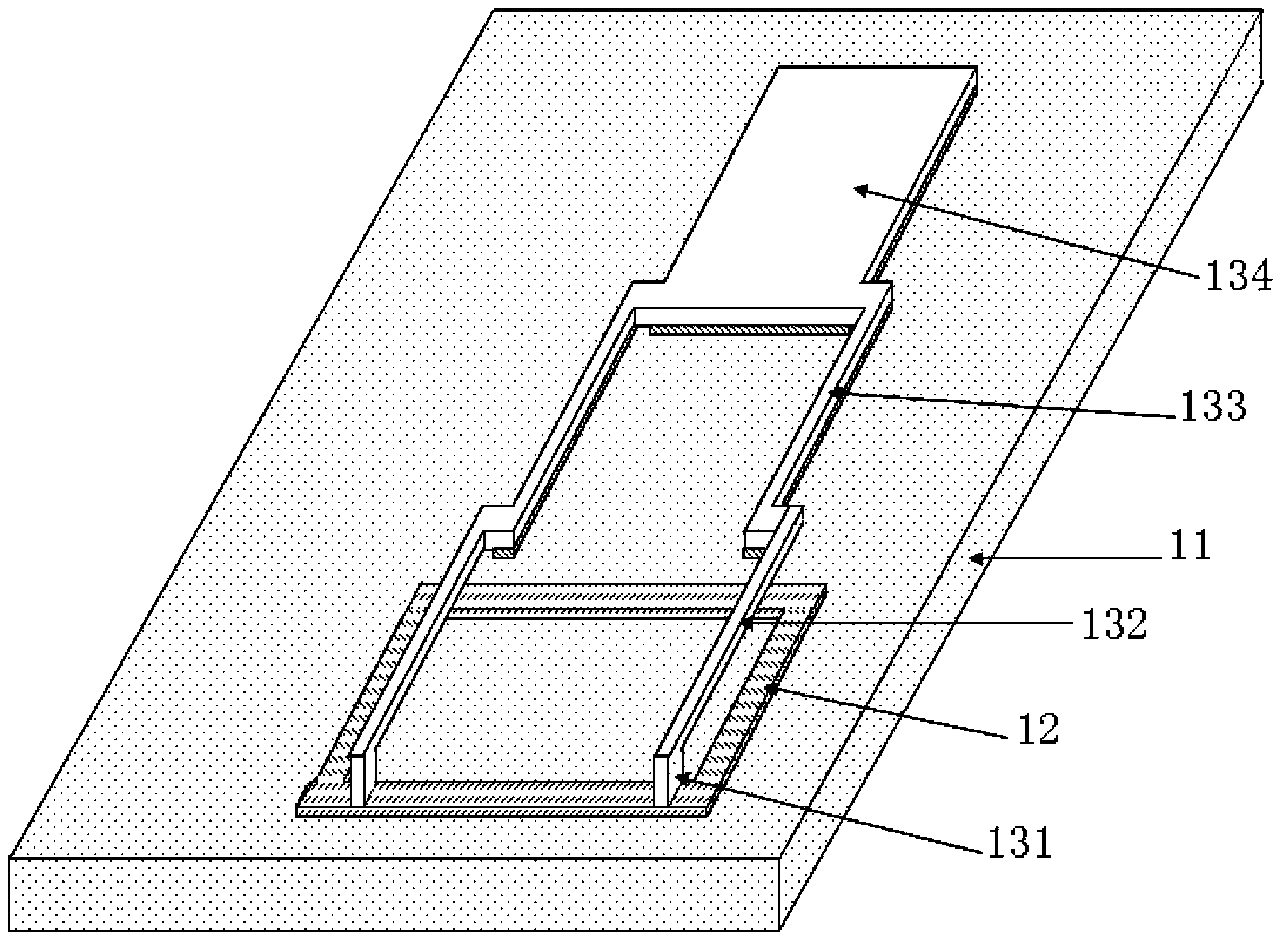
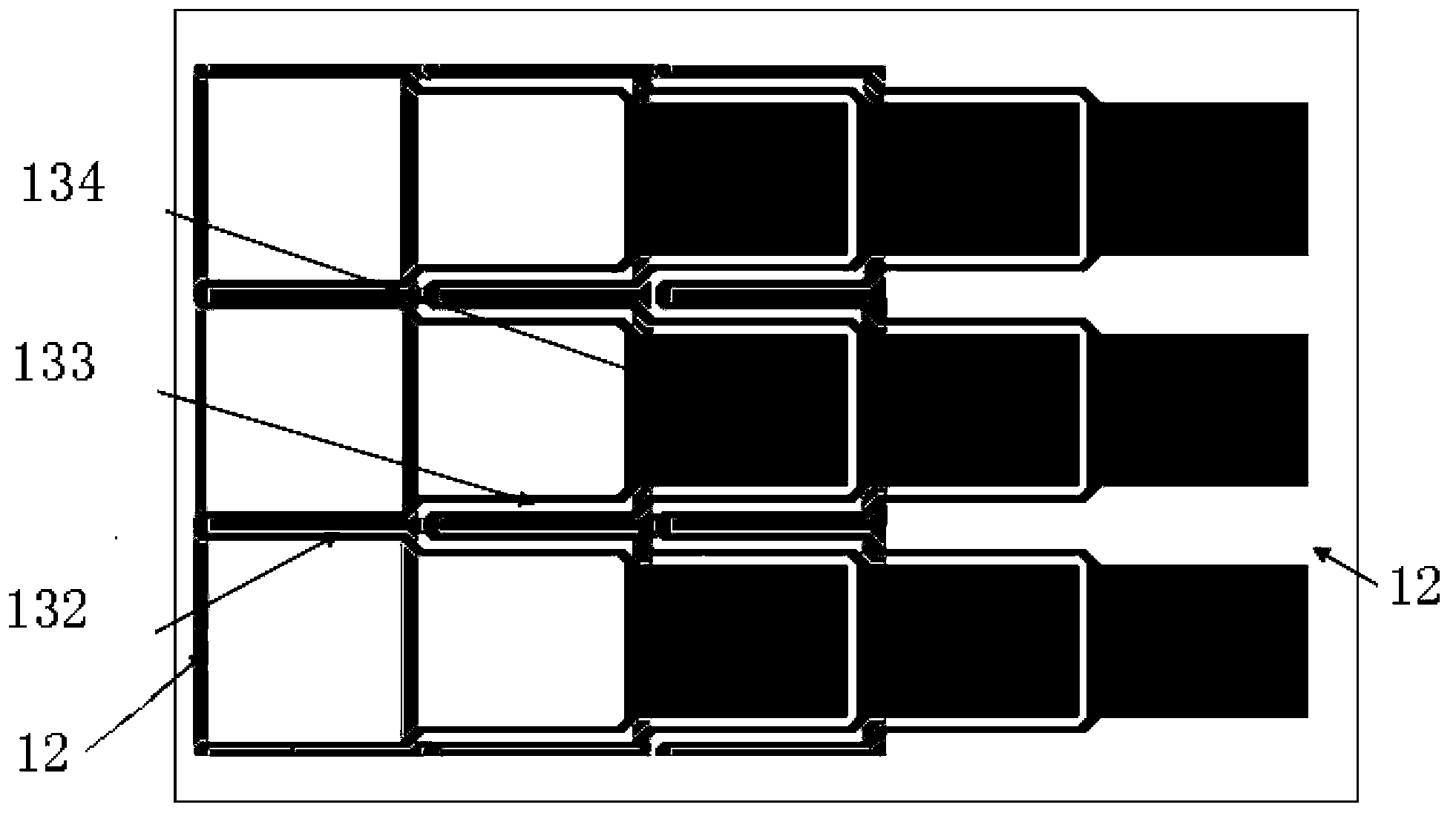
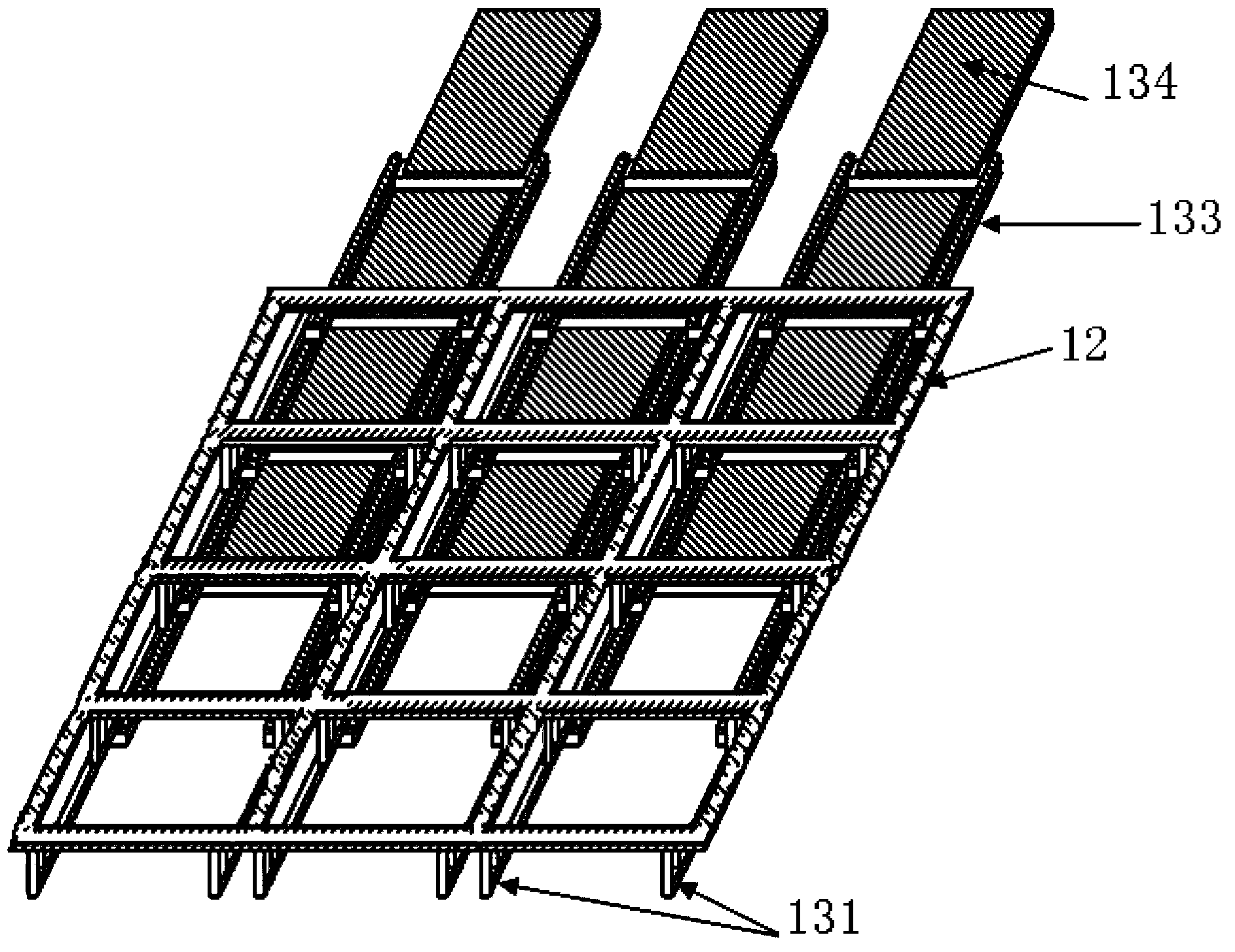
[0017] Such as figure 1 as shown, figure 1 A schematic structural diagram of an uncooled infrared imaging focal plane array detector provided by an embodiment of the present invention.

[0018] The detector includes a transparent substrate 11 , a substrate heat transfer structure 12 and a micro-cantilever beam unit 13 . Among them, a pl...


PUM


Abstract

An embodiment of the invention provides a non-refrigeration infrared imaging focal plane array detector comprising a transparent substrate, a substrate heat transfer structure with a high thermal-conductance coefficient and a micro-cantilever unit, wherein the micro-cantilever unit is laid on the transparent substrate through the substrate heat transfer structure in a nested manner. The micro-cantilever unit comprises a thermal deformation structure, a reflector board composite structure and a supporting structure. A double-material structure is adopted for the reflector board composite structure, wherein one side, which faces the transparent substrate, of the reflector board composite structure is made of a metal material; and one layer, which faces a target object, of the reflector board composite structure is made of a material with a high infrared absorption coefficient. When the target object is detected through the detector, infrared light from the target object directly irradiates to an infrared absorption layer of the detector, thereby improving measuring sensitivity. Additionally, because of the transparent substrate adopted in the detector, emptying of the substrate below the micro-cantilever unit is not required, and thus the technique complexity is reduced.

Description

technical field [0001] The invention relates to the technical field of infrared imaging detectors, in particular to an uncooled infrared imaging focal plane array detector. Background technique [0002] All objects with a temperature higher than absolute zero can produce infrared radiation, and the intensity and energy distribution of the radiation are related to the temperature of the object, and carry the characteristic information of the object. By detecting the infrared radiation of objects, it can convert the invisible infrared picture into a visible image. [0003] Common infrared detection devices can generally be divided into two types: quantum infrared radiation detectors and thermal infrared radiation detectors. Among them, the quantum infrared detector directly converts the photon energy of infrared radiation into electronic energy, while the thermal infrared detector captures infrared information by detecting the temperature change of the detector caused by the ...

Claims


Application Information

Patent Timeline
IPC IPC(8): G01J5/00G01J5/02
Inventor 高超群焦斌斌刘瑞文尚海平陈大鹏叶甜春
Owner INST OF MICROELECTRONICS CHINESE ACAD OF SCI
Why Eureka
Try Eureka