High-power LED heat resistance measuring device and method of measuring high-power LED heat resistance thereby
A measurement device and high-power technology, which is applied in the direction of single semiconductor device testing, etc., can solve the problems of low measurement accuracy of high-power LED thermal resistance measurement devices, and achieve the effects of shortening thermal equilibrium time, simple operation, and fast measurement speed
- Summary
- Abstract
- Description
- Claims
- Application Information
AI Technical Summary
Problems solved by technology
Method used
Image
Examples
specific Embodiment approach 1
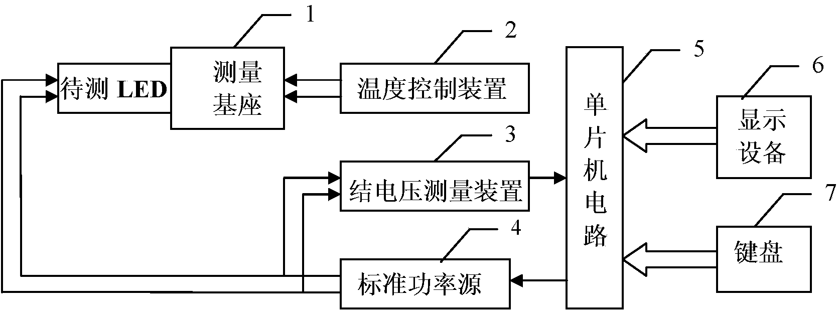
[0027] Specific implementation mode one: combine figure 1 Describe this embodiment, the high-power LED thermal resistance measurement device described in this embodiment includes a measurement base 1, a temperature control device 2, a junction voltage measurement device 3, a standard power source 4 and a single-chip circuit 5, and the measurement base 1 is a belt A base with two jacks, the temperature control device 2 is used to control the temperature of the measurement base 1, the power control signal output end of the single-chip circuit 5 is connected to the power control signal input end of the standard power source 4, and the standard power source 4 The two electrical signal output terminals of the measurement base 1 are respectively connected to the two jacks of the measurement base 1, and the two jacks of the measurement base 1 are respectively connected to the two junction voltage measurement signal input terminals of the junction voltage measurement device 3. The jun...
specific Embodiment approach 2
[0029] Specific implementation mode two: combination Figure 3 to Figure 5 Describe this embodiment, this embodiment is a further limitation of the high-power LED thermal resistance measuring device described in Embodiment 1: In this embodiment, the standard power source 4 includes an adjustable DC reference signal source and a DC power amplifier The DC reference signal output terminal of the adjustable DC reference signal source is connected to the DC reference signal input terminal of a DC power amplifier, and the DC power amplifier includes an open-loop DC power amplifier and a closed-loop feedback control circuit.
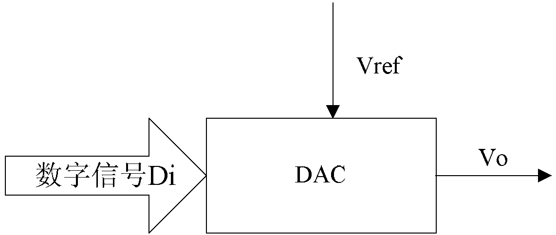
[0030] Most of the driving methods of power LEDs are constant current driving, that is, they work in the mode of constant current (marked as rated current and power). The description mainly includes adjustable DC reference signal source and DC power amplifier.
[0031] The function of the adjustable DC reference signal source is completed by two 12-bit DACs in...
specific Embodiment approach 3
[0056] Specific implementation mode three: combination figure 2 Describe this embodiment, this embodiment is a further limitation of the high-power LED thermal resistance measuring device described in Embodiment 2: in this embodiment, the accuracy of the standard power source 4 is ±0.02%, and the standard power Source 4 has two power amplifier outputs, one is the test current, the range is 0-50mA, the accuracy is ±0.02%; the other is the heating current, the range is 0-2A, the accuracy is ±0.02%.
[0057] The standard power source 4 in this embodiment has two power amplifier outputs, one is the working current If of 0-2A output, and the other is the test current (generally set as 10mA) Io of 0-50mA output. In order to achieve fast switching to improve the speed and accuracy of LED junction voltage drop measurement, the two power amplifiers can work at full load at the same time, and the two currents are switched through the output relay. Measure the LED junction voltage drop...
PUM
 Abstract
Description
Claims
Application Information
 - R&D
- Intellectual Property
- Life Sciences
- Materials
- Tech Scout
- Unparalleled Data Quality
- Higher Quality Content
- 60% Fewer Hallucinations
Browse by: Latest US Patents, China's latest patents, Technical Efficacy Thesaurus, Application Domain, Technology Topic, Popular Technical Reports.
© 2025 PatSnap. All rights reserved.Legal|Privacy policy|Modern Slavery Act Transparency Statement|Sitemap|About US| Contact US: help@patsnap.com


