Central wavelength and channel interval tunable optical-comb-shaped interferometer

A channel spacing and center wavelength technology, applied in the directions of light guides, optics, instruments, etc., can solve the problems of high cost, non-tunability of center wavelength and channel spacing, limited application, etc., to achieve low cost, simple structure, and extended application space. Effect

Inactive Publication Date: 2014-03-12
NORTH CHINA UNIVERSITY OF TECHNOLOGY
View PDF5 Cites 7 Cited by
  • Summary
  • Abstract
  • Description
  • Claims
  • Application Information

AI Technical Summary

Problems solved by technology

[0004] The technical problem to be solved by the present invention is to overcome the non-tunability, high cost, and limited application of the existing optical comb interferometer center wavelength and channel spacing, and provide an optical comb interferometer with adjustable center wavelength and channel spacing

Method used


Image

  • Central wavelength and channel interval tunable optical-comb-shaped interferometer
  • Central wavelength and channel interval tunable optical-comb-shaped interferometer
  • Central wavelength and channel interval tunable optical-comb-shaped interferometer

Examples


Embodiment approach 1

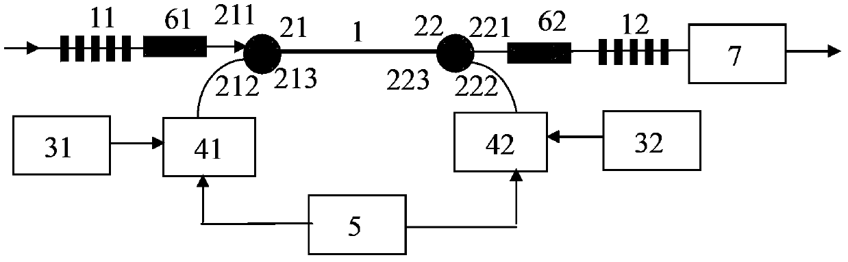
[0026] An optical comb interferometer with adjustable center wavelength and channel spacing, such as figure 1 , the interferometer includes a doped fiber 1, a first long-period grating 11, a second long-period grating 12, a first 2×1 optical coupler 21, a second 2×1 optical coupler 22, a first pump light source 31 . The second pump light source 32 , the first optical modulator 41 , the second optical modulator 42 , the signal generator 5 , the first optical isolator 61 , the second optical isolator 62 , and the optical band-stop filter 7 .

[0027] The connection of each device is as follows:

[0028] The first bifurcated port 211 of the first 2×1 optical coupler 21 is connected to the first long-period grating 11 through the first optical isolator 61, and the one-word port 213 of the first 2×1 optical coupler 21 is connected to the One end of the doped fiber 1 is connected, and the other end of the doped fiber 1 is connected with the inline port 223 of the second 2×1 optical...

Embodiment approach 2

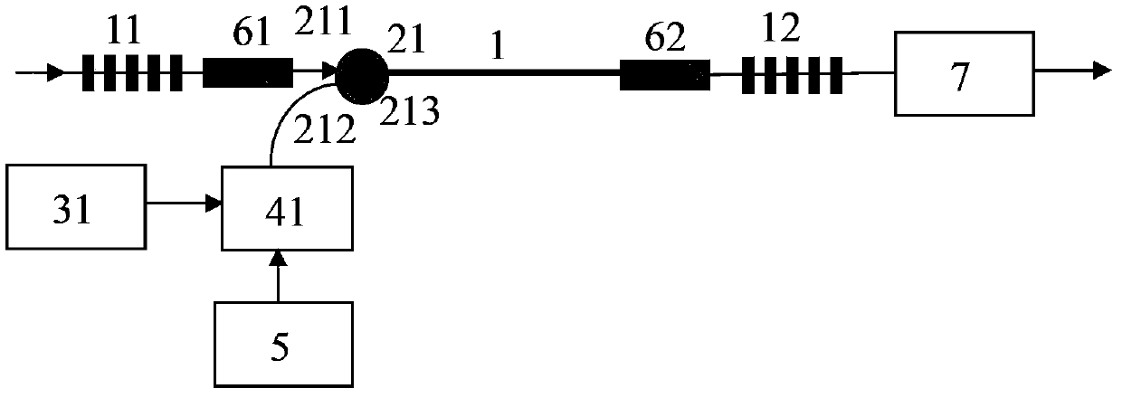
[0033] A comb interferometer with adjustable center wavelength and channel spacing, such as figure 2 , the interferometer includes a doped fiber 1, a first long-period grating 11, a second long-period grating 12, a first 2×1 optical coupler 21, a first pump light source 31, a first optical modulator 41, a signal A generator 5 , a first optical isolator 61 , a second optical isolator 62 , and an optical band-stop filter 7 . The connection of each device is as follows:

[0034] The first bifurcated port 211 of the first 2×1 optical coupler 21 is connected to the first long-period grating 11 through the first optical isolator 61, and the one-word port 213 of the first 2×1 optical coupler 21 is connected to the first long-period grating 11 through the first optical isolator 61. The doped fiber 1 and the second optical isolator 62 are connected to one end of the second long-period grating 12 , and the other end of the second long-period grating 12 is connected to the optical band...

Embodiment approach 3

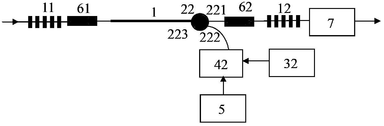
[0038] A comb interferometer with adjustable center wavelength and channel spacing, such as image 3 , the interferometer includes a doped fiber 1, a first long-period grating 11, a second long-period grating 12, a second 2×1 optical coupler 22, a second pump light source 32, a second optical modulator 42, a signal A generator 5 , a first optical isolator 61 , a second optical isolator 62 , and an optical band-stop filter 7 . The connection of each device is as follows:

[0039] The inline port 223 of the second 2×1 optical coupler 22 is connected to one end of the doped fiber 1 , and the other end of the doped fiber 1 is connected to the first long-period grating 11 through the first optical isolator 61 .

[0040] The first bifurcated port 221 of the second 2×1 optical coupler 22 is connected to one end of the second long-period grating 12 through the second optical isolator 62, and the other end of the second long-period grating 12 is connected to the optical band-stop filt...


PUM


Abstract

The invention provides a central wavelength and channel interval tunable optical-comb-shaped interferometer, which belongs to the field of fiber communication, and solves the problems of a present optical-comb-shaped interferometer including incapability of tuning the central wavelength and channel interval, high cost and limited application. In the optical-comb-shaped interferometer, the two ends of a doped fiber (1) are respectively connected in-line ports of a first 2*1 optical coupler (21) and a second 2*1 optical coupler (22), bifurcated ports (211, 221) of the first and second 2*1 optical couplers are respectively connected with a first long period grating (11) and a second long period grating (12) via a first optical isolator (61) and a second optical isolator (62), and the second long period grating is connected with an optical band-stop filter (7); and input ports of a first light modulator (41) and a second light modulator (42) are respectively connected with a first pump light source (31) and a second pump light source (32), modulation ports of the first and second light modulators are connected with a signal generator (5), and output ports of the first and second modulators are respectively connected with bifurcated ports (212, 222) of the first and second 2*1 optical couplers.

Description

technical field [0001] The invention relates to the field of optical fiber communication, in particular to an optical comb interferometer with adjustable center wavelength and channel spacing. Background technique [0002] With the rapid development of optical fiber communication technology and the maturity of multimedia communication technology, people's demand for high speed and broadband is increasing. Optical wavelength division multiplexing (WDM) can greatly reduce the cost of network construction by coupling multiple optical signals of different wavelengths into one optical fiber for transmission without setting up new optical fiber lines. However, with the continuous reduction of the channel spacing of Dense Wavelength Division Multiplexing (DWDM), the pressure on the performance of filter devices at network nodes is becoming the main obstacle restricting the further increase of the number of channels in DWDM systems. And born. [0003] The optical comb interferomet...

Claims


Application Information

Patent Timeline
Patent Type & Authority Applications(China)
IPC IPC(8): G02B6/293H04B10/25
Inventor 董小伟刘文楷王志军
Owner NORTH CHINA UNIVERSITY OF TECHNOLOGY
Why Eureka
Try Eureka