Optical comb interferometer with adjustable center wavelength and channel spacing
A channel spacing and center wavelength technology, applied in light guides, optics, instruments, etc., can solve problems such as high cost, non-tunability of center wavelength and channel spacing, and limited application, and achieve low cost, simple structure, and expanded application space Effect
- Summary
- Abstract
- Description
- Claims
- Application Information
AI Technical Summary
Problems solved by technology
Method used
Image
Examples
Embodiment approach 1
[0026] An optical comb interferometer with adjustable center wavelength and channel spacing, such as figure 1 , the interferometer includes a doped fiber 1, a first long-period grating 11, a second long-period grating 12, a first 2×1 optical coupler 21, a second 2×1 optical coupler 22, a first pump light source 31 . The second pump light source 32 , the first optical modulator 41 , the second optical modulator 42 , the signal generator 5 , the first optical isolator 61 , the second optical isolator 62 , and the optical band-stop filter 7 .
[0027] The connection of each device is as follows:
[0028] The first bifurcated port 211 of the first 2×1 optical coupler 21 is connected to the first long-period grating 11 through the first optical isolator 61, and the one-word port 213 of the first 2×1 optical coupler 21 is connected to the One end of the doped fiber 1 is connected, and the other end of the doped fiber 1 is connected with the inline port 223 of the second 2×1 optical...
Embodiment approach 2
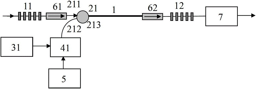
[0033] A comb interferometer with adjustable center wavelength and channel spacing, such as figure 2 , the interferometer includes a doped fiber 1, a first long-period grating 11, a second long-period grating 12, a first 2×1 optical coupler 21, a first pump light source 31, a first optical modulator 41, a signal A generator 5 , a first optical isolator 61 , a second optical isolator 62 , and an optical band-stop filter 7 . The connection of each device is as follows:
[0034] The first bifurcated port 211 of the first 2×1 optical coupler 21 is connected to the first long-period grating 11 through the first optical isolator 61, and the one-word port 213 of the first 2×1 optical coupler 21 is connected to the first long-period grating 11 through the first optical isolator 61. The doped fiber 1 and the second optical isolator 62 are connected to one end of the second long-period grating 12 , and the other end of the second long-period grating 12 is connected to the optical band...
Embodiment approach 3
[0038] A comb interferometer with adjustable center wavelength and channel spacing, such as image 3 , the interferometer includes a doped fiber 1, a first long-period grating 11, a second long-period grating 12, a second 2×1 optical coupler 22, a second pump light source 32, a second optical modulator 42, a signal A generator 5 , a first optical isolator 61 , a second optical isolator 62 , and an optical band-stop filter 7 . The connection of each device is as follows:
[0039] The inline port 223 of the second 2×1 optical coupler 22 is connected to one end of the doped fiber 1 , and the other end of the doped fiber 1 is connected to the first long-period grating 11 through the first optical isolator 61 .
[0040] The first bifurcated port 221 of the second 2×1 optical coupler 22 is connected to one end of the second long-period grating 12 through the second optical isolator 62, and the other end of the second long-period grating 12 is connected to the optical band-stop filt...
PUM
 Abstract
Description
Claims
Application Information
 - R&D
- Intellectual Property
- Life Sciences
- Materials
- Tech Scout
- Unparalleled Data Quality
- Higher Quality Content
- 60% Fewer Hallucinations
Browse by: Latest US Patents, China's latest patents, Technical Efficacy Thesaurus, Application Domain, Technology Topic, Popular Technical Reports.
© 2025 PatSnap. All rights reserved.Legal|Privacy policy|Modern Slavery Act Transparency Statement|Sitemap|About US| Contact US: help@patsnap.com


