
Retention time sequence optimization method based on multiplexing of buffer unit

A buffer unit, hold time technology, applied in special data processing applications, instruments, electrical digital data processing, etc., can solve problems such as inability to optimize timing, too high, increase design area and power consumption

Active Publication Date: 2014-03-12
NAT UNIV OF DEFENSE TECH
View PDF4 Cites 31 Cited by
  • Summary
  • Abstract
  • Description
  • Claims
  • Application Information

AI Technical Summary

Problems solved by technology

Hold-time timing violation paths are usually fixed by inserting buffer cells, however, in the later stages of the design, some paths cannot be inserted into buffer cells due to too high local cell density, and further timing optimization of the design cannot be done
At the same time, in the current design process, repairing the timing violation of the scan path and the functional data path is performed independently, resulting in repeated insertion of buffer cells in the scan path and functional data path, which increases the cell density of the design. Excessive cell density will increase the design area and Power consumption brings hidden dangers of voltage drop (IR-drop)

Method used


Image

  • Retention time sequence optimization method based on multiplexing of buffer unit
  • Retention time sequence optimization method based on multiplexing of buffer unit
  • Retention time sequence optimization method based on multiplexing of buffer unit

Examples


Embodiment Construction

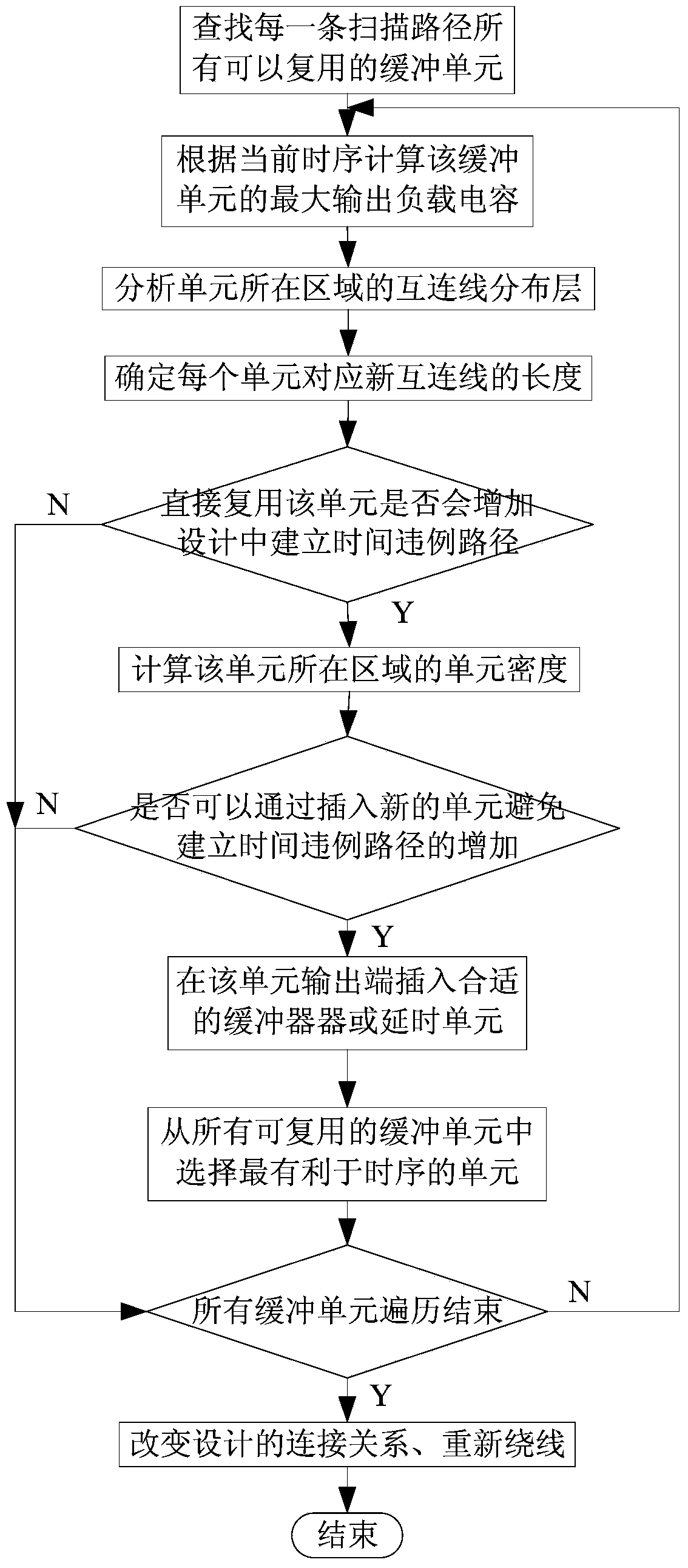
[0048] Such as figure 1 As shown, the implementation steps of the hold time sequence optimization method based on buffer unit multiplexing in this embodiment are as follows:

[0049] 1) In the design to be optimized, find the buffer units on the functional data path that have the same starting point as the scan path that holds the timing violation as reusable buffer units, and designate one of the buffer units as the current buffer unit.

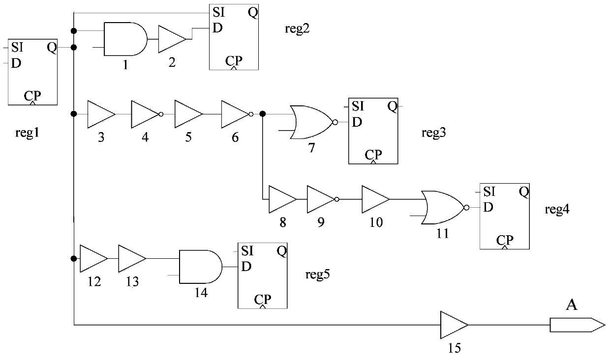
[0050] Since there may be multiple functional data paths at the same starting point, and there may also be buffer units in the port path, this embodiment divides all the functional data paths with the same starting point of the scanning path, and the logical units between the starting register and the non-buffering unit in the port path All the buffer units in between are searched, so as to find the buffer units on the functional data path with the same starting point in each scan path in the design. right figure 2 Take the path shown as ...


PUM


Abstract

The invention discloses a retention time sequence optimization method based on multiplexing of a buffer unit. The method comprises the steps: finding the buffer unit on a function data path, wherein the function data path has the same starting point with a scanning path violating the retention time sequence; determining the maximum output load capacitance of the buffer unit according to the current time sequence; determining the maximum length of an interconnection line according to the maximum output load capacitance of the buffer unit and the current wiring condition; analyzing whether a new unit is allowed to be inserted to reduce the output load capacitance of the buffer unit or not according to the local unit density of an area where the buffer unit is located if the multiplexing of the buffer unit will additionally build a time sequence violation path, and if yes, reducing the output load capacitance of the buffer unit by inserting the new unit; finally, determining the connection relationship of the scanning input end of a scanning register according to the time sequence and the physical information. The method optimizes the retention time sequence of the scanning path in design, decreases the insertion number of buffer units, and reduces the design density and power consumption.

Description

technical field [0001] The invention relates to the field of VLSI physical design, in particular to a method for optimizing hold time sequence based on buffer unit multiplexing. Background technique [0002] With the gradual reduction of the process size and the increasingly significant interconnect effect, the number of buffer cells (buffer buffer, inverter, delay cell) in the design continues to increase. Inserting buffer cells into the physical design is a common way to fix timing violations. Due to the low operating frequency in scan mode and the simple logic of the scan path, hold time timing violations usually occur in the scan path. Hold-time timing violation paths are usually repaired by inserting buffer cells. However, in the later stages of the design, some paths cannot be inserted into buffer cells due to too high local cell density, and further timing optimization of the design cannot be done. At the same time, in the current design process, repairing the timin...

Claims


Application Information

Patent Timeline
IPC IPC(8): G06F17/50
Inventor 冯超超孙秀秀赵振宇窦强乐大珩马卓马驰远余金山何小威
Owner NAT UNIV OF DEFENSE TECH
Learn More