Ignition device for spark ignition engines

A technology of ignition device and Otto engine, which is applied in the direction of ignition circuit layout, induction energy storage device, transformer/inductance parts, etc.

Active Publication Date: 2014-03-12
BORGWARNER BERU SYST
View PDF6 Cites 3 Cited by
  • Summary
  • Abstract
  • Description
  • Claims
  • Application Information

AI Technical Summary

Problems solved by technology

In addition, there is considerable heat loss in the control circuit of the

Method used


Image

  • Ignition device for spark ignition engines
  • Ignition device for spark ignition engines

Examples


Embodiment Construction

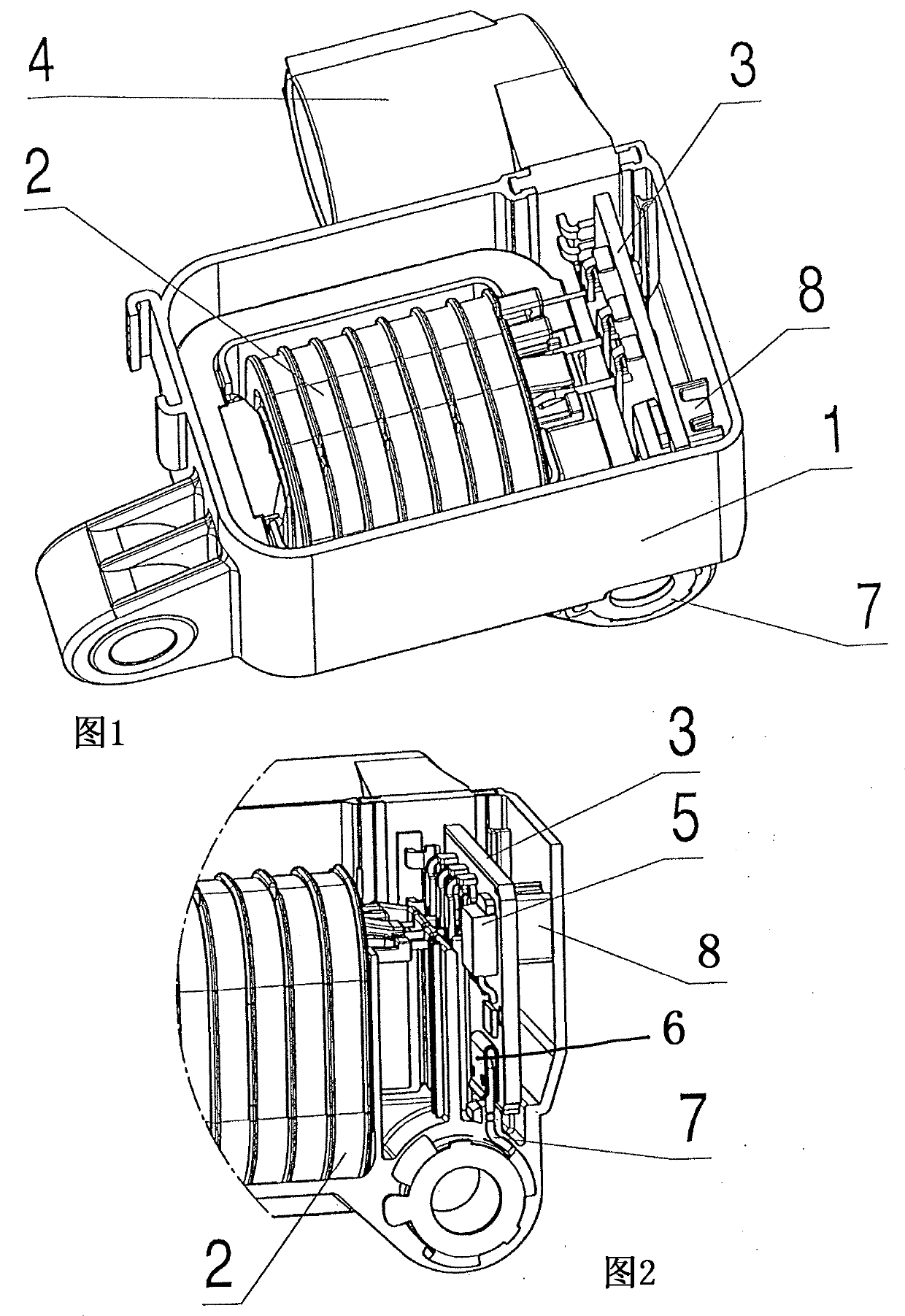
[0016] The ignition device shown has a plastic housing 1 in which is arranged an ignition coil 2 with primary and secondary windings and a printed circuit board 3 carrying a control circuit. The plastic housing 1 includes a plug connector 4 for connecting the ignition to the on-board power supply of the motor vehicle.

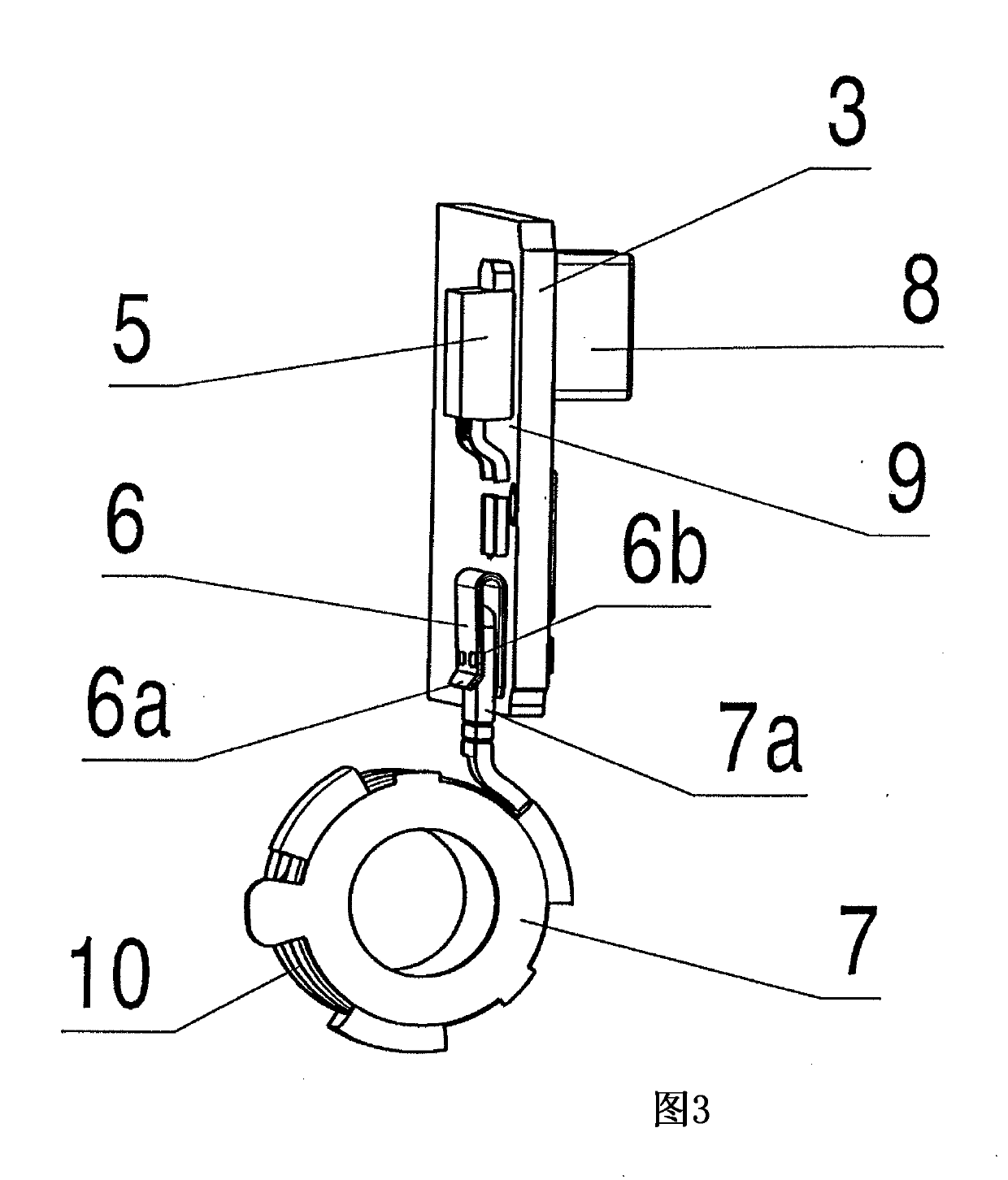
[0017] The control circuit contains power transistors 5 and thus generates considerable heat losses during operation. In order to dissipate this heat loss, the cooling body 6 is soldered, for example by SMD technology, onto the metal surface of the printed circuit board 1 , typically a copper surface. The cooling body 6 is plugged together with the heat dissipation component 7 , wherein the heat dissipation component 7 protrudes from the cavity wall of the plastic shell 1 . The cooling body 6 and the heat dissipation component 7 jointly form a thermal bridge, which dissipates the heat loss of the control circuit to the outside of the plastic casing 1 . The wa...


PUM


Abstract

The invention relates to an ignition device for an Otto engine, comprising an ignition coil (2), a printed circuit board (3), which carries a control circuit with a power transistor (5), a plastic housing (1), in which the ignition coil and the printed circuit board are arranged, and a thermal dissipation element (7), which protrudes through a wall of the plastic housing. In accordance with this disclosure, the printed circuit board (3) carries a cooling body (6), which is plugged together with the thermal dissipation element (7) to form a thermal bridge, which dissipates thermal losses of the control circuit out from the plastic housing (1).

Description

technical field [0001] The invention relates to an ignition device for a spark ignition engine. Background technique [0002] An ignition device having the features listed in the preamble of the claims of the invention is known from DE 10 2010 007 007 A1. With this type of ignition, the on-board power system voltage of the vehicle battery can be used to generate the high voltage for the spark plugs. The ignition coil of such an ignition works here on the principle of a transformer, ie it has a primary winding powered by the vehicle battery and a secondary winding connected to the spark plug. [0003] The heat losses caused by the magnetic field and the currents involved in the voltage transformation lead to a considerable temperature load on the ignition device. In addition, there is also considerable heat loss in the control circuit of the ignition device, for example caused by power transistors for switching current. [0004] Thus, for the ignition control circuit to fu...

Claims


Application Information

Patent Timeline
IPC IPC(8): H01F38/12H01F27/22
CPCF02P1/08H01F27/085H01F38/12F02P3/02H01F27/025H01F27/08F28F3/06F28F2275/14
Inventor J·魏森巴赫尔M·克劳斯S·奥伯雷尔
Owner BORGWARNER BERU SYST
Why Eureka
Try Eureka