
Radiator for concentrating photovoltaic photoelectric-converting receiver

A photoelectric conversion and concentrating photovoltaic technology, applied in the field of solar power generation, can solve the problems of increased product cost, increased cost of connecting wires and external power supply, increased production workload, etc., and achieves the effect of simple structure and low production cost

Inactive Publication Date: 2014-03-12
成都聚合科技有限公司
View PDF5 Cites 17 Cited by
  • Summary
  • Abstract
  • Description
  • Claims
  • Application Information

AI Technical Summary

Problems solved by technology

Since the light energy gathered through the lens is very strong, the working temperature on the surface of the concentrating photovoltaic photoelectric conversion receiver is very high. In order to ensure that the concentrating photovoltaic photoelectric conversion receiver can work stably within the normal temperature range, generally The photovoltaic photoelectric conversion receiver is directly bonded to the radiator, and the cooling fins at the lower end of the radiator are directly exposed to the outside air, and the heat generated by the concentrated sunlight is directly dissipated by the radiator to the outside air. The distribution of power and heat energy is done by adding a fan on the radiator, which will increase the cost of the connecting wire and external power supply in addition to the cost of the fan, as well as increase the workload of production, resulting in an increase in product cost; at the same time Since the cooling fins of the existing radiators all adopt square column structure, when the natural wind circulates through the array of square column cooling fins, the natural wind can only cool the relatively high heat on both sides of the square column cooling fins. The air is brought to the air outside the radiator by air flow for heat exchange, which causes the hot air around the heat dissipation column in the radiator to not completely exchange with the external air, which affects the heat dissipation effect of the radiator

Method used


Image

  • Radiator for concentrating photovoltaic photoelectric-converting receiver
  • Radiator for concentrating photovoltaic photoelectric-converting receiver

Examples


Embodiment Construction

[0014] The present invention will be further described below in conjunction with the accompanying drawings.

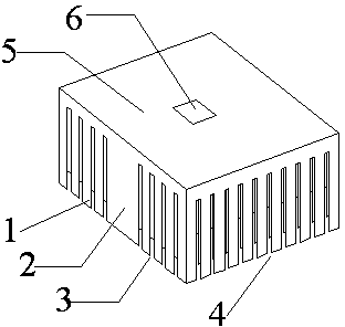
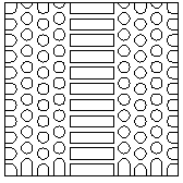
[0015] A radiator for concentrating photovoltaic photoelectric conversion receivers, such as Figure 1~2 As shown, it includes secondary cooling fins 1 , main cooling fins 2 , radiator bottom plate 5 , and installation area 6 for concentrating photovoltaic photoelectric conversion receivers. The secondary cooling fin 1 is composed of a multi-row cylindrical array or a multi-row elliptical cylindrical array and a graphic array formed by splicing the surrounding array into a square and a semicircle. The internal and surrounding arrays of the secondary cooling fin 1 are interlaced in pairs Yes, the main heat dissipation fins 2 are arranged in a row of rectangular column arrays, and there is a mounting area 6 for concentrating photovoltaic photoelectric conversion receivers on the bottom plate of the radiator 5 .

[0016] The using method of the present invention is:

[...


PUM


Abstract

The invention relates to a radiator for a concentrating photovoltaic photoelectric-converting receiver, and belongs to the technical field of solar power generation. The radiator comprises primary heat-radiating fins, secondary heat-radiating fins, a radiator soleplate and a concentrating photovoltaic photoelectric-converting receiver installing area, wherein one surface of the radiator soleplate is provided with a primary heat-radiating fin array and secondary heat-radiating fin arrays in two different shapes, and the other surface of the radiator soleplate is provided with the concentrating photovoltaic photoelectric-converting receiver installing area. The radiator disclosed by the invention has the advantages of simple structure and low manufacturing cost; natural wind can be guaranteed to enter the inner part of the radiator as much as possible through the surrounding arrays of the secondary heat-radiating fins of the radiator; the natural wind can be refracted in different directions at the inner part of the radiator when acting on the internal cylinder or elliptic-cylinder arrays of the secondary heat-radiating fins, and meanwhile, hot air at a higher level is brought to staggered heat-radiating arrays at a lower level in the mode of airflow flowage, so that the natural wind entering the heat-radiating fins is guaranteed to bring more hot air in the radiator to the air outside the radiator to be exchanged through many times of refraction and circulation, and therefore the heat radiation and the cooling for the radiator are guaranteed to be furthest carried out through the natural wind.

Description

technical field [0001] The invention relates to a photovoltaic heat dissipation component, in particular to a heat sink for a concentrating photovoltaic photoelectric conversion receiver, which belongs to the technical field of solar power generation. Background technique [0002] The concentrated photovoltaic photoelectric conversion receiver is the core component of the concentrated photovoltaic power generation system, which is used to directly convert the light energy gathered by the lens into electrical energy. Since the light energy gathered through the lens is very strong, the working temperature on the surface of the concentrating photovoltaic photoelectric conversion receiver is very high. In order to ensure that the concentrating photovoltaic photoelectric conversion receiver can work stably within the normal temperature range, generally The photovoltaic photoelectric conversion receiver is directly bonded to the radiator, and the cooling fins at the lower end of t...

Claims


Application Information

Patent Timeline
Patent Type & Authority Applications(China)
IPC IPC(8): H02S40/42
CPCY02E10/50
Inventor 王永向丁刚李仁春
Owner 成都聚合科技有限公司
Learn More