Valveless piezoelectric micromixer for synthesizing jet

A technology of synthetic jet and micro-mixer, which is applied in mixers, chemical instruments and methods, dissolution, etc., can solve the problems of mixing controllability, poor mixing effect, low mixing efficiency, and failure of synthetic jet, etc. Control, improve mixing efficiency, and strengthen mixing effect

Inactive Publication Date: 2014-03-19
JIANGSU UNIV
View PDF5 Cites 22 Cited by
  • Summary
  • Abstract
  • Description
  • Claims
  • Application Information

AI Technical Summary

Problems solved by technology

[0005] The purpose of the present invention is to propose a kind of synthetic jet valveless piezoelectric micro-mixer in order to overcome the deficiencies existing in the existing active micro-mixer, it is mainly aimed at the existing problems of the existing micro-mixer such as low mixing efficiency, Due to poor mixing controllability and mixing

Method used


Image

  • Valveless piezoelectric micromixer for synthesizing jet
  • Valveless piezoelectric micromixer for synthesizing jet
  • Valveless piezoelectric micromixer for synthesizing jet

Examples


Embodiment Construction

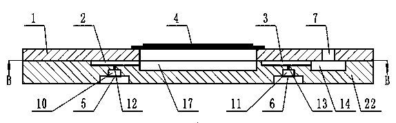
[0024] Such as figure 1 , 2 , 3, 4, 10, and 11, the present invention integrates a microfluidic driving unit (ie, a piezoelectric pump) and a microfluidic mixing unit (ie, a mixing channel). It includes a pump cover 1, a pump body 22, a synthetic jet actuator and a piezoelectric vibrator 4. The pump inlet 8, the pump inlet 9, the upper part of the pump cavity 17 and the pump outlet 7 are processed on the pump cover 1 by using MEMS technology. The pump inlet 8 and the pump inlet 9 are located at the left part of the pump cover 1, and are respectively connected with inlet pipelines. The pump outlet 7 is located at the right part of the pump cover 1, and is externally connected to the outlet pipeline. The upper half of the pump cavity 17 is in the middle of the pump cover 1 .

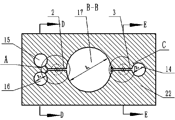
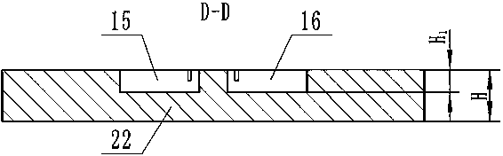
[0025]In the upper part of the pump body 22, the inlet mixing channel 2 and the outlet mixing channel 3 with the same structure, two inlet buffer chambers 15, 16 with the same structure, an outlet buff...


PUM

PropertyMeasurementUnit
Widthaaaaaaaaaa
Heightaaaaaaaaaa

Abstract

The invention discloses a valveless piezoelectric micromixer for synthesizing jet, comprising a pump cover and a pump body which are bonded together, wherein two synthesis jet chambers are communicated with a relative inlet mixing flow path and a outlet mixing flow path, a first piezoelectric vibrator is fixed right above the pump cover, each of a second piezoelectric vibrator and a third piezoelectric vibrator is fixed right below the two synthesis jet chambers respectively, the inlet mixing flow channel and the outlet mixing flow channel are Y-type mixing flow channels each of which is composed of two shunting flow channels and a shunting flow channel, a jet synthesis exciter is arranged on the bottom of the mixing flow channel of the micromixer, fluid flow in the mixing flow channel is interfered by periodically ejecting and absorbing fluid by synthesis jet, and alternating voltage signal applied on the piezoelectric oscillator is regulated to implement large-range controllable mixing of mixed effect and mixed time.

Description

technical field [0001] The invention relates to a micro-fluid mixer in a micro-fluid machine, in particular to a valveless piezoelectric micro-mixer capable of mixing micro fluids and controlling the flow direction. Background technique [0002] The unique geometric characteristics, flow characteristics and transfer characteristics of the microfluidic system determine its advantages: small reaction volume, high conversion efficiency, low reactant consumption, high safety performance, etc. The application of technology and chemical reaction kinetics is getting more and more in-depth. Microfluidic systems include microreactors, micromixers, microvalves, micropumps, microheat exchangers, microsensors, etc., where micromixers can be used as microsensors for biochemical analysis instruments and for biochips and microvolumes. The mixing of different specimens and different reagents in the chemical analysis and detection system is used for rapid mixing and microinjection of drug...

Claims


Application Information

Patent Timeline
IPC IPC(8): B01F13/00
Inventor 何秀华蔡盛川邓志丹韦丹丹
Owner JIANGSU UNIV
Why Eureka
Try Eureka